Day 2
Interfaces, Cables & Link Diagnosis
interfaces-cables-diagnosis
At a glance
Diagnose copper and fiber link faults from negotiated settings and counters: collisions, CRC, runts, giants, duplex and speed mismatch, pinout, cable type, signal level, polarity, and distance. Interface types, straight-through and crossover, Auto-MDI-X, and what a link means in Packet Tracer versus real hardware sit underneath that diagnosis. Maps to CCNA v2.0 objective 1.1.
Deep chapter
Long-form companion reading (original prose).
Day 2 in context: physical layer literacy
Day 1 gave you the cast: hosts, switches, routers, firewalls, wireless. Day 2 is where you learn the stage rigging—interfaces, transceivers, copper and fiber standards, cable categories, negotiation, and the first disciplined troubleshooting ladder. Many outages that look like “routing” are actually wrong media, bad ports, or speed/duplex mismatch.
By the end of this chapter you should read a port label like “Gi1/0/24” without panic, pick a sensible copper standard for a desktop uplink versus a distribution uplink at a high level, and explain why console access is not interchangeable with user Ethernet.
How IEEE names Ethernet: BASE, speed, and media
IEEE 802.3 defines Ethernet at the physical and data-link layers (with MAC rules you study more on switching days). The shorthand you see in books and exams usually follows a pattern: a speed number, the word BASE meaning baseband (no frequency-division multiplexing like some WAN radios), and a media code—T for twisted pair, TX for a specific copper PHY variant, SX/LR for fiber, and so on.
Each PHY is standardized in an IEEE 802.3 amendment (or clause incorporated into the base standard). Exams increasingly mix marketing names (1000BASE-T) with clause numbers (802.3ab). Learn both: the letter in the PHY name hints at the medium; the amendment number hints at the speed generation.
Important nuance: the number is the line rate on the wire (raw PHY speed), not guaranteed TCP throughput. Protocol overhead, inter-frame gaps, hosts, and congestion all reduce what applications feel.
Twisted-pair Ethernet PHY standards (what shows up on CCNA)
These rows are the copper (UTP/STP) PHYs you are most likely to compare in coursework and multiple-choice framing. Distances assume a compliant twisted-pair channel (horizontal cable, connectors, patch leads) per TIA-568-style structured cabling—not a random fly lead coiled above a ceiling tile.
Memory hook by amendment: 802.3i → 10BASE-T; 802.3u → 100BASE-TX (same amendment as 100BASE-FX fiber); 802.3ab → 1000BASE-T; 802.3an → 10GBASE-T; 802.3bz → 2.5GBASE-T and 5GBASE-T. The classic exam trap remains 802.3ab (gigabit copper) vs 802.3z (gigabit fiber SX/LX)—different media, different amendments.
Legacy 100BASE-T4 (also 802.3u) used four Cat3 pairs; modern plant is overwhelmingly 100BASE-TX on two pairs. If a stem mentions T4, think old horizontal cabling and four-pair 100 Mb/s—not what you install today.
| IEEE PHY | 802.3 amendment | Common label | Line rate | Typical twisted-pair | Typical max channel (guide) |
|---|---|---|---|---|---|
| 10BASE-T | 802.3i | Ethernet on UTP | 10 Mb/s | Cat3 minimum in the old spec; Cat5 common today if found | 100 m |
| 100BASE-TX | 802.3u | Fast Ethernet (copper) | 100 Mb/s | Cat5 UTP (two pairs used for data) | 100 m |
| 1000BASE-T | 802.3ab | Gigabit Ethernet on copper | 1 Gb/s | Cat5e or better; all four pairs participate | 100 m |
| 2.5GBASE-T | 802.3bz | Multigig / NBASE-T | 2.5 Gb/s | Often Cat5e for shorter runs; Cat6 for comfortable 100 m class designs | Up to ~100 m on Cat6 (design-dependent) |
| 5GBASE-T | 802.3bz | Multigig | 5 Gb/s | Cat6 common for 100 m-class links | ~100 m on solid Cat6 (vendor tables vary) |
| 10GBASE-T | 802.3an | 10 Gigabit on copper | 10 Gb/s | Cat6a common for 100 m; Cat6 may work shorter | 100 m on Cat6a typical campus answer |
Pairs, duplex, and why Gigabit needed four pairs
Classic Fast Ethernet 100BASE-TX uses two pairs: one direction per pair in full duplex. Gigabit on copper (1000BASE-T) uses all four pairs simultaneously with echo cancellation and sophisticated coding—so an old “two-pair only” cable fault that still passed 100 Mb/s might fail at 1 Gb/s.
Full duplex on a switch port means the port can transmit and receive at the same time without classic collision-domain sharing. Half duplex still exists in theory on some links; mismatch with a full-duplex peer is a historic pain that shows up as interface errors and miserable performance.
TIA cable categories (bandwidth class, not “speed” by itself)
Category ratings define cable performance: tighter twists, better isolation, higher usable frequency. Higher category does not automatically “upgrade the internet”; it means the copper plant can support higher PHYs at required distances with acceptable bit error rates.
| Category | Class bandwidth (≤100 m) | Typical Ethernet you plan for | Notes |
|---|---|---|---|
| Cat3 | 16 MHz | Legacy voice / very old 10BASE-T plant | Mostly obsolete for new LANs |
| Cat5 | 100 MHz | 100BASE-TX; marginal for 1000BASE-T long term | Superseded by Cat5e in practice |
| Cat5e | 100 MHz (tighter specs than Cat5) | 1000BASE-T standard answer | Most common “existing building” cable |
| Cat6 | 250 MHz | 1 Gb/s everywhere; shorter 10GBASE-T possible | Lower crosstalk than Cat5e |
| Cat6a | 500 MHz | 10GBASE-T at 100 m design target | Common for new horizontal runs |
| Cat7/7a | 600–1000 MHz | Shielded solutions; less common wording on CCNA | Know it exists; vendor marketing varies |
| Cat8 | 2000 MHz | Short copper in data centers (25/40GbE variants) | Not typical access-layer desktop cabling |
RJ-45, pinouts, and structured cabling vocabulary
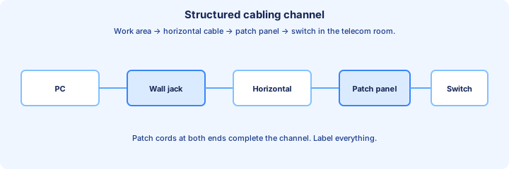
The modular 8-position 8-contact plug/jack is commonly called RJ-45 in networking speech. T568A vs T568B are color-code orders for the eight conductors; consistency matters end-to-end. A horizontal cable run usually terminates on a patch panel (permanent link) and is patched to a switch with a short patch cord (channel).
Bad terminations, stretched pairs, and tight bend radii raise return loss and crosstalk—symptoms look like “flaps at 1 Gb/s but fine at 100 Mb/s.”
MDI vs MDI-X, straight-through, crossover, Auto-MDI-X
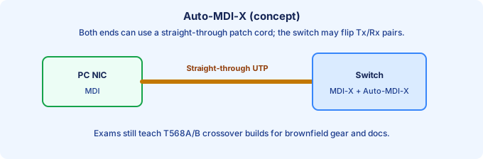
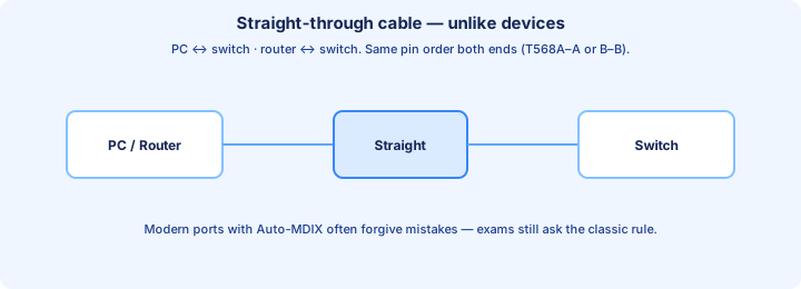
Ethernet NICs and switch ports expect transmit and receive on specific pin pairs. A crossover cable swaps those pairs so like devices could interconnect in early designs. A straight-through cable keeps pin order end-to-end for unlike devices (host to switch).
Auto-MDI-X lets modern interfaces detect and flip pairs in silicon so crossover cables are rarely needed in new installs. CCNA still tests the classical story because you will still read old diagrams, work in brownfield closets, and troubleshoot someone’s “mystery cable drawer.”
Pinout, pair count, and cable type
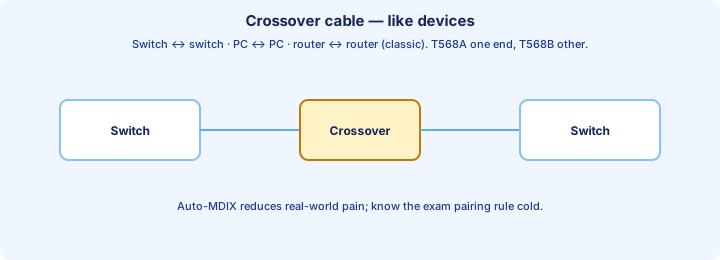
Pinout decides whether a copper link can come up before speed and duplex ever negotiate. T568A on both ends is a straight-through cable. T568B on both ends is also straight-through. A on one end and B on the other swaps the pair on pins 1-2 with the pair on pins 3-6, which is a crossover. Hosts and modern switches hide that swap with Auto-MDI-X. A port with `no mdix auto`, or an old switch that never had it, still needs the classical cable: straight-through between unlike devices, crossover between like devices. A rollover cable is a console cable. It will not light an Ethernet data port.
1000BASE-T trains on all four pairs. A run that only punches down pairs 1-2 and 3-6 can still carry 10 or 100 Mb/s and then fail, or fall back, when the port tries to negotiate 1 Gb/s. Split pairs, where the two wires of a logical pair are not the twisted partners, often pass a cheap continuity tester and still produce CRC errors and flaky negotiation. The channel length for twisted-pair Ethernet is 100 meters, patch cords included. Past that length the link drops, errors, or negotiates downward.
Exam trap: “no link” between two switches is still a cable-type question when the stem mentions legacy hardware or Auto-MDI-X turned off. “Link up at 100, errors or no link at 1000” is a pair-count or distance question. Compare both ends, and the punch-down, before you replace the switch.
UTP (Unshielded Twisted Pair): pairs, plugs, and why twists matter
Most access-layer Ethernet in offices uses UTP: four pairs of copper conductors twisted together inside a PVC jacket, with no metallic foil shield around each pair (hence unshielded). Twisting fights crosstalk and electromagnetic pickup; tighter twist rates and better insulation are how higher cable categories support higher frequencies.
Shielded twisted pair (STP / F/UTP, S/FTP, etc.) appears in noisy industrial sites or some data centers. CCNA still centers UTP vocabulary: Cat5e/Cat6/Cat6a horizontal cabling, RJ-45 plugs, patch panels, and compliance testing (NEXT, return loss) in real installs.
A modular plug terminates all eight conductors according to T568A or T568B color order. New North American installs commonly standardize on T568B end-to-end for consistency. The cable type (straight vs crossover) is about whether pin 1 on the left electrically reaches pin 1 on the right, or whether transmit/receive pairs swap for like-device links.
Fiber optics: what you are actually plugging in
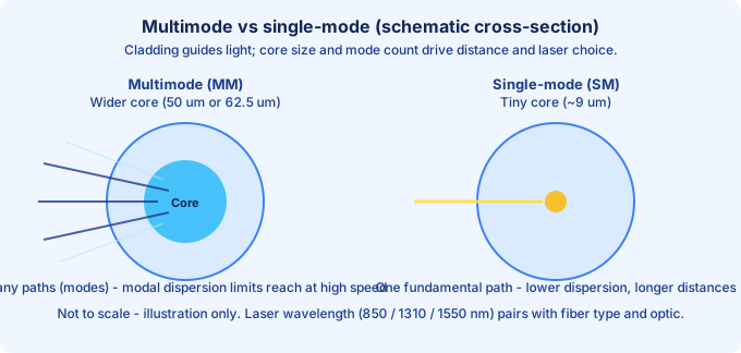
Fiber carries light through a glass core surrounded by a lower-index cladding so rays (modes) stay guided. Compared with copper, fiber wins on distance and immunity to electrical noise; it loses on cost of optics, skill to terminate cleanly, and sensitivity to dirt. CCNA expects you to pair the right IEEE PHY name (for example 1000BASE-SX) with multimode vs single-mode, typical wavelength, and rough distance class—not to design an optical budget spreadsheet.
Those PHY names live under the parent standard IEEE 802.3. Each speed generation is published as an amendment you will see on datasheets and exam stems: 802.3u (Fast Ethernet, including fiber 100BASE-FX), 802.3z (Gigabit over fiber—1000BASE-SX and 1000BASE-LX), 802.3ae (10 Gigabit fiber PHYs such as 10GBASE-SR/LR/ER), and 802.3ba (40 and 100 Gigabit fiber families). Do not confuse 802.3z (gigabit fiber) with 802.3ab, which is 1000BASE-T on twisted pair.
A duplex link uses two strands (or two lanes in a ribbon) so each side can transmit while the other receives. Polarity mistakes (A/B flipped) are a classic “both optics good, no link” field issue.
Wavelengths and why installers talk in nanometers
850 nm is the common multimode window for short-reach optics (LEDs in the past; VCSELs today). 1310 nm and 1550 nm appear heavily in single-mode systems; 1550 nm is often used for longest WAN spans with amplifiers. The exam usually stops at recognizing that SX/SR family is 850 nm MM while LR/LX on SM is long-wavelength territory.
You cannot freely mix wavelengths: each transceiver is built for a band. Color-coded bales on LC connectors sometimes help techs avoid plugging a blue SM patch into an MM plant—but always read the module label and data sheet.
Multimode grades (OM1–OM5) at a glance
Multimode fiber is classified by OM (optical multimode) grade. Newer OM grades support higher modal bandwidth, which translates to longer 10/40/100 Gb/s reaches at the same wavelength. Legacy 62.5 µm OM1 still exists in old buildings; most greenfield is laser-optimized 50 µm OM3/OM4, with OM5 adding wider WWDM support for certain high-speed schemes.
| Grade | Core (typical) | Exam / field note |
|---|---|---|
| OM1 | 62.5 µm | Legacy; shorter high-speed reach than OM3/OM4 |
| OM2 | 50 µm (older) | Better than OM1; still limited vs laser-optimized grades |
| OM3 | 50 µm laser-optimized | Common data center / campus MM for 10G SR class |
| OM4 | 50 µm | Extended MM reach vs OM3 at high speeds |
| OM5 | 50 µm (wide) | Know the name; less detail on CCNA than OM3/OM4 |
Single-mode (OS1/OS2) and when engineers pick it
Single-mode cable is yellow in many plant conventions. OS1 vs OS2 is a construction/loss class story for standards people; for CCNA, internalize “SM + LR optics = campus/metro distances MM cannot hit.” SM optics cost more but avoid modal dispersion limits that cap MM distance as speeds rise.
Mode-conditioning patch cords can allow some gigabit LX optics to launch into legacy MM more safely; if you see the term on a question, think “LX + MM nuance,” not day-to-day access-layer design.
Connectors, polish, and physical mistakes that kill links
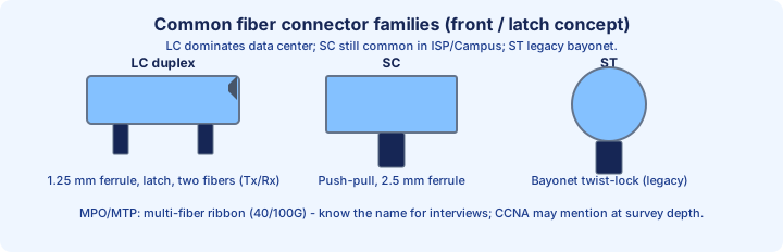
LC duplex is the de facto data center connector: small form factor, latch, two ferrules. SC remains common in ISP handoffs. ST is older bayonet style you still see in plant photos. MPO/MTP carries parallel ribbons for 40/100 Gb/s short reach—know the acronym for interviews even if the lab stays on LC SR optics.
Fiber faces must stay clean: oil from a thumbprint or dust creates back reflections and loss. UPC polish is typical in enterprise LAN; APC (green-bodied connectors, angled polish) appears in CATV/PON contexts—do not mix APC and UPC in the same mated pair.
Fiber signal, polarity, and distance
A dark fiber link is often light, polarity, or the wrong optic, which objective 1.1 groups with signal level and distance. The transmit strand on one end must land on receive at the other. A swapped duplex LC connector, or a polarity flip in a cassette, leaves both ports with no link even though each SFP is healthy. `show interfaces transceiver` (and `detail` on platforms that expose DOM) reports Tx and Rx power against the optic’s thresholds. Rx below the low warning means too much loss: distance past the optic’s budget, a dirty end-face, too many patches, a bend tighter than the cable’s radius, or a strand that is simply broken.
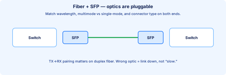
Wavelength and mode have to match on both ends. A 1310 nm long-reach optic will not train with a 850 nm short-reach optic. Multimode fiber under a single-mode optic, or the reverse, may fail outright or may link across a short jumper and then fall apart on the real run. Distance is part of the PHY: 1000BASE-SX is hundreds of meters depending on the OM grade, while LX/LR and single-mode runs are measured in kilometers. Exceeding the budget raises CRC errors before it becomes a total blackout. Clean the end-face and confirm the optic part number against the fiber type before you swap the switch.
Exam trap: one side showing receive light and the other showing none is a polarity or a break, and it is evidence you can read. Replacing both SFPs without reading Rx power burns a change window. UDLD can catch a unidirectional fiber later; the first check is still light, connector polarity, wavelength, and distance.
Pluggable optics: SFP, SFP+, QSFP, and DAC twinax
Field-replaceable modules let one switch SKU serve copper access, fiber uplinks, or long-reach SM. SFP ≈ 1 Gb/s class; SFP+ ≈ 10 Gb/s; QSFP variants aggregate lanes for 40/100 Gb/s. Direct-attach copper (DAC) uses twinax with fixed module ends for very short rack-to-rack links—cheaper and lower latency than fiber when distance allows.
A missing module, wrong speed grade, or incompatible optic (MM SR plugged into an SM-only path) shows up as a dark interface or stuck notconnect even though configuration looks perfect. Always verify part numbers against the cable plant.
Loss, bend radius, and operations hygiene
Every connector, splice, and split adds insertion loss; budgets add those losses against the optic’s power budget. Sharp bends (below vendor minimum radius) cause macro-bending loss—especially at tighter wavelengths. If a cable is kinked in a door, fix the bend before you chase VLANs.
Use dry cleaning tools or lint-free wipes approved for optics; blowing on a connector is folklore, not engineering. Label both ends of the same fiber pair so polarity tracing does not become a two-hour mystery.
IEEE fiber Ethernet PHYs (exam-oriented survey)
Associate each row with three ideas: the marketing PHY (1000BASE-SX), the 802.3 amendment that standardized it, and the fiber type / wavelength that must match your plant. The table is not every clause in 802.3—only the fiber silhouettes that show up in coursework and multiple-choice framing.
Memory hook by speed era: 802.3u → 100 Mb/s fiber (FX); 802.3z → 1 Gb/s fiber (SX/LX); 802.3ae → 10 Gb/s fiber (SR/LR/ER and related); 802.3ba → 40/100 Gb/s parallel optics (SR4, LR4, etc.). Later amendments (802.3by for 25G, 802.3bm for refined 40/100G modules) matter in data centers but are usually survey depth on CCNA.
| IEEE PHY | 802.3 amendment | Common name | Fiber / λ (typical) | Distance class (guide) |
|---|---|---|---|---|
| 100BASE-FX | 802.3u | Fast Ethernet fiber | MM 1310 nm (2 fiber strands) | ~2 km MM (legacy plant) |
| 1000BASE-SX | 802.3z | Gig short wavelength | MM 850 nm | Tens to hundreds of meters (OM grade dependent) |
| 1000BASE-LX | 802.3z | Gig long wavelength | SM 1310 nm (MM with caveats) | Longer than SX; SM spans dominate |
| 10GBASE-SR | 802.3ae | 10G short reach | MM 850 nm | Data center / risers per OM3/OM4 table |
| 10GBASE-LR | 802.3ae | 10G long reach | SM 1310 nm | Much longer campus/metro than SR (~10 km class) |
| 10GBASE-ER | 802.3ae | 10G extended reach | SM 1550 nm | Longer than LR at survey depth (~40 km class) |
| 10GBASE-LRM | 802.3aq | 10G long reach multimode | MM 1310 nm | Extends MM plant for 10G when OM budget allows (~220 m guide) |
| 40GBASE-SR4 | 802.3ba | 40G short reach (4 lanes) | MM 850 nm (often MPO) | Data center MM; lane count matters |
| 40GBASE-LR4 | 802.3ba | 40G long reach (4 λ on SM) | SM 1310 nm WDM | Campus/metro SM when MM distance is exhausted |
| 100GBASE-SR4 | 802.3ba | 100G short reach (4 lanes) | MM 850 nm (often MPO) | High-speed MM spine; know name + amendment |
| 100GBASE-LR4 | 802.3ba | 100G long reach (4 λ on SM) | SM 1310 nm WDM | Survey: SM answer when stems ask longest 100G fiber hop |
Router and switch interfaces on Cisco IOS (naming and state)
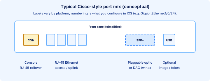
Interface names encode type and numbering: GigabitEthernet0/0, TenGigabitEthernet1/1, TwentyFiveGigE, Serial0/0/0, etc. The exact slot/port layout is platform-specific, but the configuration grammar is stable: interface x/y, description, speed, duplex, shutdown/no shutdown.
show ip interface brief lists IP-enabled routed interfaces succinctly; show interfaces status is gold for switch access ports (connected/notconnect, speed, duplex, VLAN). Learn both early.
Console and VTY: management planes vs user data plane
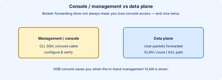
Console is out-of-band serial-style access for bootstrap and recovery. VTY lines are for remote sessions (SSH/Telnet). Neither replaces routed Ethernet for carrying user subnets; confusing console with a normal switchport is a classic lab derail.
SSH replaces Telnet because encryption and integrity matter even inside a “trusted” management VLAN—attackers move laterally.
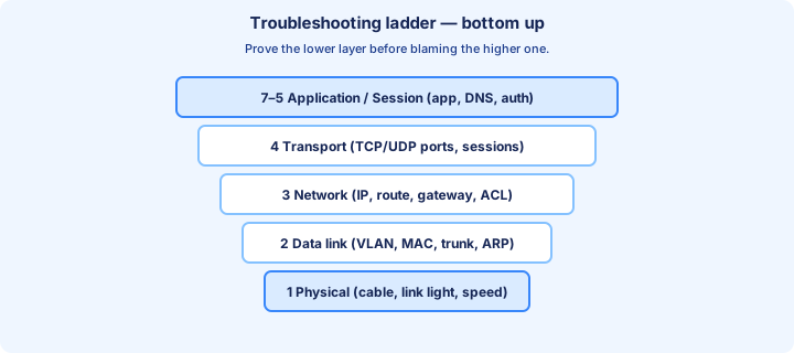
Troubleshooting ladder (memorize this order)
1) Link light and interface status. 2) Correct media and module. 3) Speed/duplex negotiation evidence. 4) Cable category vs attempted PHY. 5) VLAN/access vs trunk (later). 6) IP and mask. 7) Routing. 8) ACL/NAT (later). Randomly skipping rungs wastes hours.
Counters that name the fault
Objective 1.1 lives in `show interfaces`, not in the routing table. Read the negotiated speed and duplex, then the counters, on both ends. Collisions belong to half duplex. On a full-duplex switched port they should stay at zero. Late collisions, frames that collide after the 512-bit window, are the classic signature of a duplex mismatch: one side forced to full, the other left on auto and fallen back to half. The link stays up. Throughput collapses. CDP often logs the mismatch if both ends speak it.
CRC and input errors mean the frame failed its FCS: bad cable, noise, a failing NIC, split pairs, or that same duplex mismatch. Runts are undersized frames, often from collisions or bad hardware. Giants are oversized frames: an MTU mismatch, or a tagged frame landing on a port that is not expecting the extra four bytes. Output drops and queue drops mean congestion, which is a different ticket from a bad pair. `clear counters` on the interface, generate traffic, and read again so last year’s errors do not convict today’s cable.
Speed that is forced to different values on the two ends often produces no link at all. Auto on one side and `duplex full` with a forced speed on the other is the mismatch that stays up. The safe patterns are auto on both ends, or the same manual speed and duplex on both ends. Exam trap: a green link with rising late collisions is a duplex and counter problem. Do not start at OSPF.
Connecting Devices lab: what to rehearse
Rebuild the topology twice from blank: first slow with notes, second timed. After each link-up, say aloud the PHY speed you expect given cable labels in the exercise (even if simulated). If the lab offers copper vs fiber uplinks, write one sentence on why an engineer would pick fiber for that hop.
Into Day 3
With standards tables in your notebook, the OSI and TCP/IP models become grounded: physical layer is not abstract when you can name the PHY and the cable class that must support it.
Key ideas
- Late collisions and CRC on a port that claims full duplex point at a duplex mismatch or a bad pair. Compare both ends, then clear counters and retest.
- Both ends auto, or both ends the same manual speed and duplex. Auto on one side and forced full on the other leaves the link up and half duplex on the auto side.
- T568A and T568B are straight-through when both ends match. Mixing them builds a crossover. 1000BASE-T needs four pairs inside 100 meters. A rollover cable is for the console.
- Fiber fails on low Rx power, swapped Tx/Rx polarity, wrong wavelength or mode, and distance past the optic. Read show interfaces transceiver before you swap hardware.
- Console access is out-of-band management. It is a different cable and a different port from user Ethernet.
Self-check
- A switch port shows half duplex and rising late collisions while the PC is forced to full. What do you change, and on which ends?
- The run links at 100 Mb/s and will not train at 1000. Which physical facts do you check?
- Rx power is below the low warning on one optic and healthy on the other. Name two causes.
- When does a crossover still matter if most of your switches have Auto-MDI-X?