Day 3
The TCP/IP Model
tcp-ip-model
At a glance
TCP/IP is what we build/run; OSI is the teaching map. Learn PDU names, encapsulation direction, and where common problems sit (DNS vs routing vs duplex). Maps to CCNA v2.0 objective(s) 1.0.
Deep chapter
Long-form companion reading (original prose).
Why Day 3 exists: shared language for every later topic
Networking is taught in layers because responsibilities are separable. You can swap a cable plant without rewriting HTTP. You can fix a routing loop without caring which cipher suite TLS negotiated. Day 3 installs the vocabulary that lets you read exam questions, RFC titles, and packet captures without drowning in undifferentiated octets.
You will see two reference models side by side. The OSI model (seven layers) is the classroom map: clear boundaries and memorable PDU names. The TCP/IP model (four layers) is how RFCs and operators usually talk. CCNA mixes them on purpose. Your job is quick translation, not arguing which one is more real—both describe the same bits crossing NICs and routers.
Carry one mental rule through all later days: which layer changed last? That question turns vague "the network is slow" into testable hypotheses (duplex vs DNS vs TLS vs queue drops).
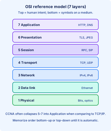
The TCP/IP model: four buckets engineers actually say aloud
Network access collapses OSI physical and data link: NICs, drivers, Ethernet, Wi-Fi, PPP. Internet is mostly IP and ICMP—the hop-by-hop logical graph. Transport is TCP and UDP: ports, segments, windowing, checksums. Application quietly swallows OSI session, presentation, and application whenever someone says "Layer 7 problem."
Why keep both maps? TCP/IP matches how code ships: sockets, routing daemons, kernel forwarding tables. OSI matches how exams carve wording. When a question says "PDU at Layer 2," it expects the OSI envelope name, not a loose "packet."
When you whiteboard two hosts, draw the TCP/IP stack on sticky notes for speed, then annotate which OSI layers each box touched. That habit prevents memorizing seven numbers without being able to explain what happens when you ping by name versus by IP.
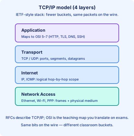
Encapsulation and decapsulation: direction matters
When an application sends bytes, the operating system hands them to the stack. Each layer adds headers and sometimes trailers (for example Ethernet FCS). By the time traffic leaves the NIC, it is structured bits on a medium. Encapsulation walks downward: the payload from layer N+1 becomes the data field inside layer N's PDU.
Along the path, devices read only what they are built for. A switch port typically parses Ethernet headers for forwarding; a router parses IP for forwarding while still needing correct Layer-2 framing for each hop. Decapsulation on the receiving host walks upward: strip Ethernet, deliver IP, strip IP, deliver TCP or UDP, deliver payload to the correct socket.
Wireshark habits start here: the outermost decoded row is the lowest layer in that hop's capture. Nested rows are inner headers. If you invert the mental direction, you will misread who dropped the frame versus who dropped the packet.
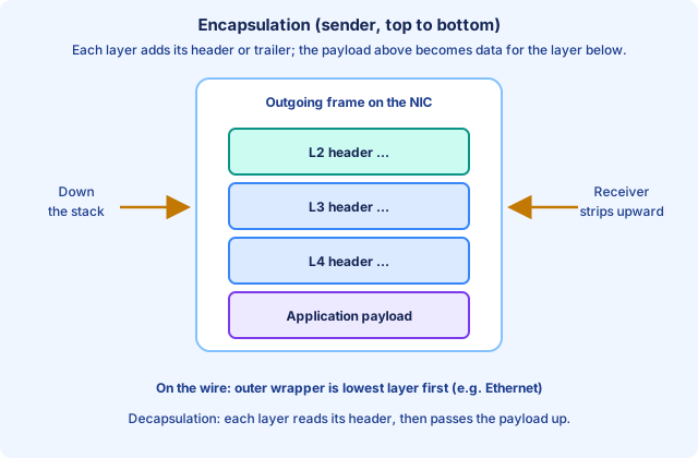
PDU names: memorize once, profit for months
PDU means protocol data unit—the name of the chunk at a layer before the next layer wraps it. Common CCNA mapping: upper-layer payload is often called data; TCP uses segment; UDP uses datagram; IP uses packet; Ethernet uses frame; the physical medium carries bits (symbols).
Spoken English says "packet" for almost everything. Exam writers reward precision. If a stem asks for the Layer-2 PDU, frame is the word. If it asks what a router routes at Layer 3, think packet carrying IP.
Encapsulation ties PDU names together: a segment is encapsulated inside a packet, which is encapsulated inside a frame. On each router hop, the frame header is rebuilt while the packet header (usually) survives until destination IP processing—another preview of why MAC and IP both exist.
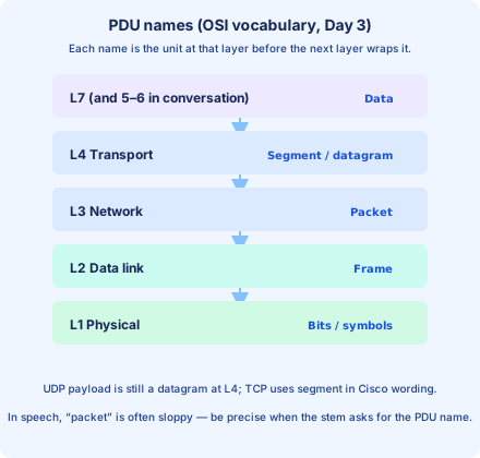
OSI layers 1 and 2: medium, framing, and one LAN hop
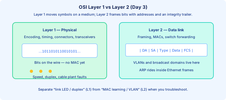
Layer 1 (physical) is signaling, encoding, connectors, transceivers, port speed and duplex, and the raw bit stream. It answers how symbols move across copper, fiber, or radio—not which MAC should receive a frame. Classic UTP Ethernet negotiates timing with the link partner; physical problems show up as errors, flaps, or autonegotiation surprises before the switch parses a clean frame.
Layer 2 (data link) frames those bits: destination and source MAC addresses, switching decisions, broadcast and unknown-unicast flooding inside a broadcast domain, and an FCS so corrupted frames can be discarded. Switches are predominantly Layer-2 devices for access traffic. MAC learning is hop-by-hop: each switch builds its own table from source addresses it sees.
Troubleshooting hygiene: separate link LED, speed, duplex, cable (physical) from MAC learning, VLAN membership, STP state (data link). Mixing the two layers is how hours disappear. ARP is worth a bookmark: it carries IP-related information but rides inside Ethernet frames—exams love that boundary.
OSI layer 3: logical addressing and routing scope
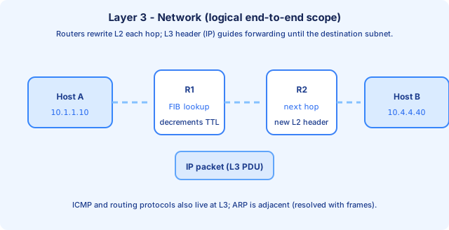
Layer 3 (network) is IPv4 and IPv6 logical addressing, routing tables, longest-prefix forwarding, TTL handling, and ICMP alongside IP. Hosts use Layer 3 to decide whether traffic is local or should go to a default gateway. Routers connect subnets and forward based on destination IP.
Each router hop typically rewrites the Layer-2 header while keeping the Layer-3 packet coherent (NAT aside for now). That is why MAC addresses are not an internet-wide routing scheme: they identify delivery on a segment, while IP identifies participation in the routed graph.
When ping to an IP works but ping to a hostname fails, you are often looking above Layer 3. When ping to a remote IP fails, you may still be at Layer 3 (routing) or below (ARP not resolving on the local segment). Layer isolation is a triage lens, not a religion—use it to pick the next command.
OSI layer 4: multiplexing, ports, and reliability choices
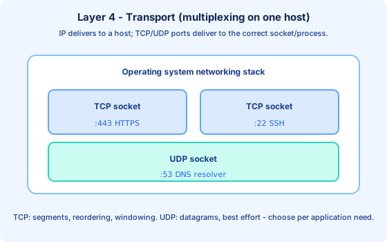
Layer 4 (transport) is TCP and UDP on the exam. TCP offers connection setup, reordering, retransmission, and flow control—segment-based. UDP is best-effort and message-oriented—datagram language. Both use 16-bit port numbers so many applications can share one IP address.
When someone says "the port is closed," that is usually a socket or firewall policy story at transport (and policy enforcement may also live on a stateful device). When someone says "window full," that is TCP flow control, not Ethernet bandwidth alone.
Sockets combine IP + protocol + port. That tuple is how the operating system demultiplexes arriving traffic to the correct process—multiplexing many conversations on one NIC.
OSI layers 5, 6, and 7: session, presentation, and application
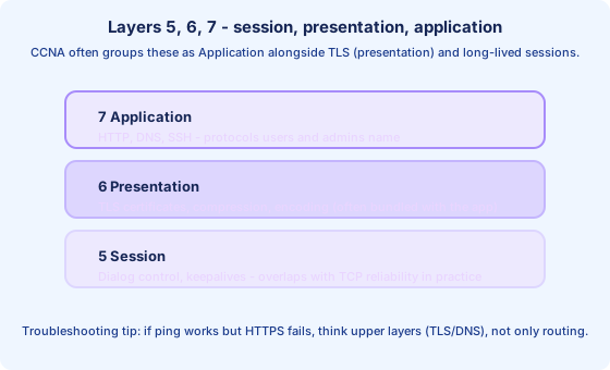
Textbooks separate session (dialog control), presentation (encoding and encryption), and application (HTTP, DNS, SMTP, SNMP). TCP/IP teaching often collapses all three into application for speed. CCNA cares less about naming session versus presentation than about recognizing TLS, compression, and HTTP failures as different from routing failures.
Still learn the OSI labels: they appear in glossaries, interview questions, and older documentation. If HTTPS fails but HTTP works, think presentation-ish (certificates, cipher suites). If a long file transfer dies at steady intervals, think session keepalives or middleboxes—after you have ruled out interface errors and path MTU.
Practical drill: for each user-visible symptom, write two candidate layers and one `show` or capture filter that would confirm or deny each. That is how the model becomes operational.
Mapping OSI to TCP/IP on one sketch
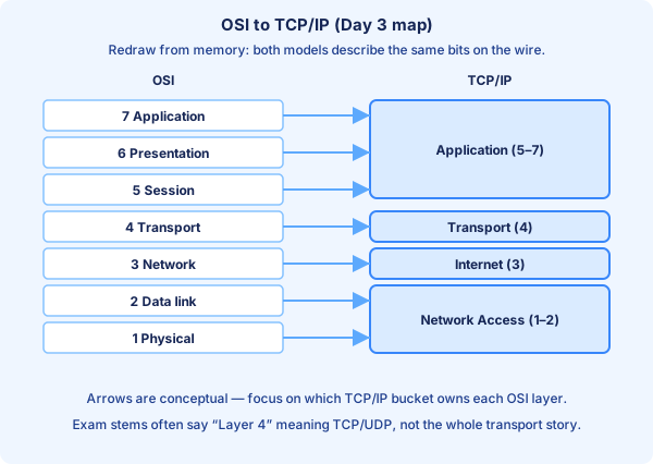
Network access = OSI 1 + 2. Internet = OSI 3. Transport = OSI 4. Application = OSI 5 + 6 + 7 in most conversations. Saying "Layer 4" almost always means TCP/UDP; saying "Layer 2" almost always means Ethernet framing and switching.
Draw two columns, OSI on the left and TCP/IP on the right, and trace curved arrows from 5-7 into Application, 4 into Transport, 3 into Internet, and 1-2 into Network access. If you can redraw that in ninety seconds on paper, you have absorbed the day's hardest rote skill.
When documentation says "host-to-host," it often means transport and below. When it says "end-to-end," clarify whether they mean IP end-to-end or application end-to-end—marketing language drifts.
The OSI model lab: turn labels into examples
Attach a concrete protocol or tool to each layer: ICMP rides with IP at Layer 3; ARP resolves next-hop addresses using frames at Layer 2; TCP handshake segments live at Layer 4; HTTP and DNS live in application space. If your lab uses Packet Tracer simulation events, narrate which header changed for each step.
Add one capture exercise: filter `icmp` or `tcp.port == 443` and point at the outer Ethernet row, the IP row, and the TCP row. The goal is not memorizing field widths yet—it is automatic layer identification.
If your course provides an OSI ordering game or flash cards, use them once, then retire them in favor of topology narration: "ARP flood here is Layer 2 scope inside the VLAN; default gateway missing is Layer 3 on the host."
Common misconceptions to kill early
Misconception: MAC addresses route the internet. They do not. MAC addresses matter hop-by-hop on Ethernet; routers forward using IP prefixes. NAT adds another story later, but MACs are still not global internet locators.
Misconception: TCP guarantees the application is happy. TCP can deliver bytes to a socket buffer while your app still mis-parses JSON or fails auth. Reliability is transport-scope, not business-logic scope.
Misconception: One layer equals one device. A router participates in Layers 1-3; a host runs all seven in software. The model describes responsibilities, not chassis counts.
Misconception: Strict OSI purity in every sentence. Real engineers mix models; exams sometimes require OSI wording. Learn both dialects.
Bridge into Day 4 (CLI)
Once you can speak layers, CLI output becomes organized: `show interfaces` is largely physical and data link; `show ip route` is network; socket listings on hosts are transport-shaped; application troubleshooting returns to ping-by-name versus ping-by-IP patterns. You are now allowed to enjoy the CLI because it maps to a model.
Key ideas
- Encapsulation adds headers as data moves down; decapsulation removes them going up.
- Layer isolation is a troubleshooting mindset: which layer changed last?
Self-check
- Name PDUs from Application down through Ethernet at a CCNA level.
- Is ARP 'Layer 2' or 'Layer 3 adjacent'? Be ready to explain in your own words.