Day 37
LAN Architectures
lan-architectures
At a glance
LAN architectures: two-tier vs three-tier, access/distribution/core roles, and collapsed-core tradeoffs. Maps to CCNA v2.0 objective(s) 2.0, 1.2.
Deep chapter
Long-form companion reading (original prose).
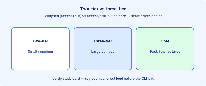
Two-tier three-tier
Three-tier campus design uses access, distribution, and core layers. Access connects endpoints; distribution aggregates access and applies policy; core moves traffic fast between distribution blocks and to the WAN/DC edge. Three-tier shines when many distribution blocks need a stable, policy-light core for east-west traffic.
Two-tier (collapsed) merges distribution and core into one layer—common in medium sites where a separate core adds cost without benefit. Access still exists; only the upper layers collapse. Two-tier cuts latency and devices by collapsing aggregation; watch CPU/TCAM on the collapsed pair.
Choose by scale: many buildings and high east-west traffic favor a dedicated core. A single building with a pair of aggregation switches usually stays two-tier. If you cannot explain why a dedicated core exists, you probably want collapsed core instead.
Exam trap: “two-tier” does not remove the access layer. It collapses distribution+core, not access+everything.
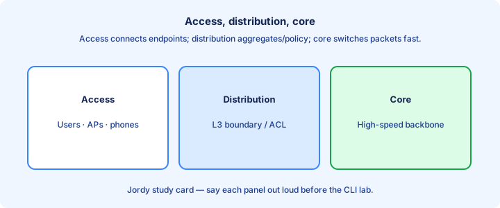
Access distribution core
Access: port security, VLAN assignment, PoE, edge QoS marking, wireless AP attachment. Keep STP and broadcast domains as small as design allows. Access is where Days 49–51 security features actually attach to user jacks.
Distribution: L3 routing (or multilayer), summarization, ACLs, FHRP gateways for access VLANs, aggregation of links. This is where policy and IP boundaries often live, and where building aggregates summarize toward the core.
Core: high-speed redundancy, minimal policy, stable IGP. Avoid stretching user VLANs across the core unless you have a clear reason—L3 core is the usual exam preference for scale. Core should avoid terminating random access VLANs.
Exam trap: putting user access ports on core switches. Cores do not terminate PCs in a clean hierarchical design. Feature placement by layer is a favorite exam diagram skill.
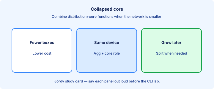
Collapsed core
A collapsed core pair runs both distribution and core jobs: L3 gateways for access VLANs, stacking or VSS/StackWise-style pairing, and uplinks to WAN routers or firewalls. The pair acts as one logical aggregation point for dual-homed access switches.
Benefits: fewer boxes, simpler cabling, lower cost. Risks: the collapsed pair becomes a larger failure domain and a busier policy point—capacity planning matters because it carries distribution policy and core transit together.
Redundancy still uses dual uplinks from each access switch to both collapsed-core members. Do not single-home access switches if you care about uplink failure. Every access switch should uplink to both members.
Exam trap: collapsed core is still hierarchical. Drawing a random mesh of access switches is not “collapsed core”—it is a loop farm.
L2 vs L3 boundary
The L2/L3 boundary is where SVIs or routed ports begin—and where VLANs stop stretching. Placing the boundary at distribution (L2 access, L3 distribution) is classic. Routed access pushes L3 to the access switch. Classic trunks on access, SVIs on distribution, routed links above.
L2 access is simple for printers and legacy gear but extends STP and broadcast domains. L3 access contains failures and speeds convergence with IGP, at the cost of more routing and first-hop design on the edge. STP diameter shrinks when the L3 boundary moves closer to users.
On diagrams, find where VLAN IDs stop and subnet hop starts. That hop is where FHRP usually sits in L2-access designs. Pure L3 access may use different first-hop patterns than HSRP on distribution SVIs.
Exam trap: “VLAN across two buildings through the core” usually screams bad L2 stretch unless the stem justifies it. Prefer L3 boundaries between buildings.
Oversubscription
Oversubscription is the ratio of potential downstream bandwidth to uplink capacity—for example forty-eight 1G access ports feeding a 2×10G uplink pair is a planning ratio, not a promise of congestion. Campus designs accept oversubscription because endpoints rarely burst together at line rate.
Access-to-distribution ratios are higher; core links stay closer to 1:1. Wireless AP uplinks and WAN edges need their own math—do not reuse the same ratio blindly. Measure with interface utilization and drop counters during backup windows.
When users complain of slow backups at night, check uplink utilization and buffer drops, not only client NICs. Oversubscription shows up as congestion, not as a down interface. Capacity planning language on the exam is oversubscription—not “QoS” alone.
Exam trap: oversubscription is a capacity design term, not a security feature or an STP mode.
Campus design
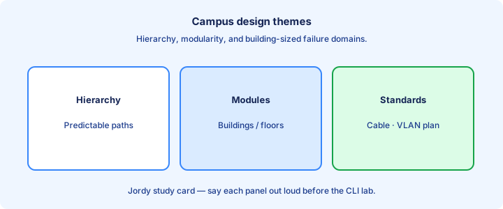
Good campus design is hierarchical, modular, and redundant where failure domains matter. Building blocks (floors, IDFs) look alike so templates and troubleshooting repeat at 2 a.m. Repeatable IDF templates beat artisanal one-off closets.
Addressing should follow the hierarchy: summarize at distribution toward the core. Random /24s everywhere defeat summarization and lengthen IGP tables. Summarize building aggregates so the core IGP stays small.
Separate user, voice, wireless AP, and management VLANs/subnets with intent. Shared flat VLAN campuses are exam anti-patterns for anything beyond a tiny site. Flat VLAN growth is technical debt that every later security feature has to paper over.
Exam trap: adding a new building by extending one giant VLAN “to keep it simple” creates the largest possible failure domain.
Wireless integration
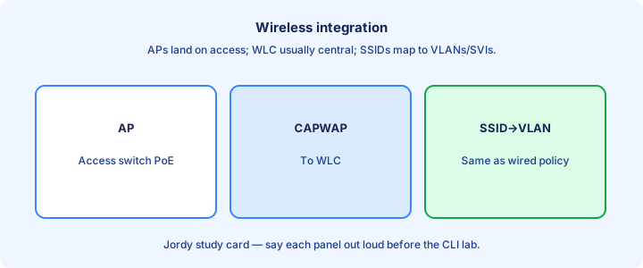
APs usually sit on access switches with PoE, often in an AP VLAN, tunneling or switching user traffic per design (local switching vs central CAPWAP themes). The wired access port still needs the right VLAN and often trust for QoS. PoE budget is part of campus capacity planning for AP-dense floors.
Controllers (WLC) attach higher in the hierarchy—distribution/core/DC—depending on scale. User SSIDs map to VLANs/SVIs that must exist where traffic is bridged or anchored. CAPWAP changes where user traffic tunnels, not the need for clean SSID-to-VLAN maps.
Do not treat wireless as a separate mystery network: RF ends as Ethernet. Capacity, security, and gateway placement still follow campus rules. Guest SSIDs should hit firewalls/VRFs, not the same SVI as corporate laptops.
Exam trap: plugging APs into random user VLANs without a plan mixes guest and corporate traffic at L2. Day 55 covers RF; today place APs and controllers correctly on the wired diagram.
Redundancy patterns
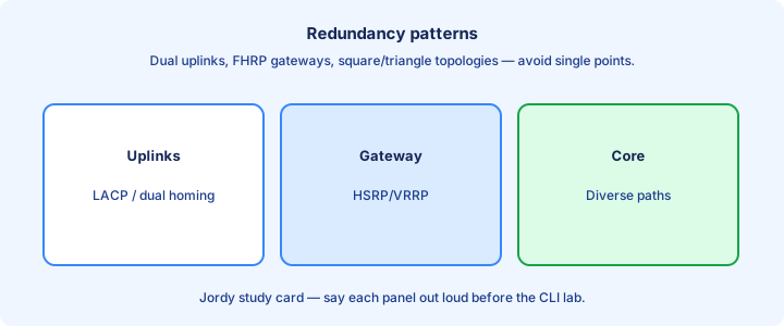
Classic pattern: dual distribution/core switches, access dual-homed, FHRP for gateways, EtherChannel for link aggregation, STP as safety for remaining L2. L3 equal-cost multipath where both uplinks are routed avoids STP blocking on those links.
Square/triangle topologies between distribution and core provide alternate paths. Avoid partially meshed designs that look redundant but funnel all traffic through one oversubscribed link. EtherChannel to one upstream is link resiliency; dual switches are device resiliency—you need both stories.
Test failover: shut an uplink and confirm convergence with `show ip route`, FHRP state, and user pings. Redundancy that was never failed over is hope, not design. Scheduled failover tests belong in acceptance criteria.
Exam trap: two cables in the same EtherChannel to the same upstream switch do not protect against that upstream switch dying—you need two upstream devices.
Exam diagrams
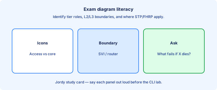
On exam diagrams, label layers first: which icons are access, distribution, core, WAN edge. Then mark L2 vs L3 links (trunk vs routed). Then find gateway SVIs and FHRP. Circle the L3 hops; everything inside a circle is one STP/VLAN risk domain.
Questions often ask where to place a feature: port security at access, summarization at distribution, high-speed switching at core, VPN at WAN edge. Wrong layer = wrong answer. Misplacing ACLs on core instead of distribution is a common layer error.
Count failure domains: one access switch down should not kill the campus. One core down should leave an alternate path. If the drawing cannot survive that, the design is weak. Ask which failure the question cares about—uplink, switch, or WAN.
Exam trap: mistaking a firewall icon for a distribution switch and placing user VLANs behind the wrong hop.
Lab map your site
Lab exercise: sketch your real or Packet Tracer site as access/distribution/core (or collapsed). Mark every trunk, routed link, SVI, and FHRP VIP. List oversubscription guesses on uplinks. Color trunks versus routed links so L2 stretch cannot hide in your own drawing.
Identify one change that shrinks an L2 domain (move a VLAN gateway, add routed access, split a fat VLAN). Identify one redundancy gap (single-homed IDF). If you lack a real site, map two buildings and force an L3 boundary between them.
Build a mini three-switch collapsed-core lab: two “collapsed” switches + one access. Dual-home the access switch and fail an uplink while pinging across SVIs. Roles beat hostnames—rename devices Access1/Dist1 if names confuse you.
Exam trap: mapping devices by hostname only. Map by role; names lie, roles decide features.
Failure domains
A failure domain is what breaks when one component dies: a VLAN spanning three buildings is one huge L2 failure domain. An L3 boundary per building contains broadcast storms and STP events. A storm in a stretched VLAN can freeze phones three buildings away—that is the blast radius lesson.
Power, uplink, switch chassis, and WAN circuits are separate domains. Dual PSUs do not fix a single uplink. Dual uplinks do not fix a missing FHRP peer. Independent domains include power circuit, switch chassis, uplink bundle, WAN circuit, and wireless controller.
Design to localize: STP events stay in one access block; IGP reconvergence handles the rest. Document blast radius for each single point of failure you accept. Accepted single points of failure must be named explicitly—silence means denial.
Exam trap: equating “redundant” with “no failure domain.” Redundancy shrinks impact; it does not make domains vanish.
Migration notes
Migrating flat L2 to hierarchical L3: introduce distribution SVIs, move gateways off ancient core switches, then break inter-building trunks into routed links. Move VLANs in batches, not all at once. Move gateways to distribution SVIs before you sever inter-building trunks.
Keep FHRP VIPs stable so endpoints do not need re-addressing when chassis change. Summarize only after addressing is cleaned—summarizing chaos creates black holes. Keep VIP addresses stable so DHCP scopes and static gateways survive chassis swaps.
During migration, temporary hybrid designs exist (some VLANs still stretched). Document them with an end date so “temporary” trunks do not become permanent. Temporary VLAN stretches need calendar expiry or they become the permanent design.
Exam trap: migration questions still want the target hierarchical design as the best answer, not the transitional mess.
Checklist
Two-tier vs three-tier chosen with a reason. Access/distribution/core roles stated. Collapsed core understood. L2/L3 boundary marked on a diagram with trunks versus routed links colored.
Oversubscription concept clear. Wireless attachment noted. Redundancy is dual-device, not dual-cable-only. Failure domains identified for your lab map with blast radius named.
Exam diagram read order practiced: layer → link type → gateway. Migration direction toward hierarchy between buildings. Capstone sketch ready.
Exam trap check: can you point to where port security vs OSPF vs VPN each belong on a three-tier drawing?
Capstone LAN
Capstone: design a two-building campus. Building A collapsed-core pair; Building B access + distribution; L3 link between buildings; FHRP in each building for local VLANs; APs on access with separate VLAN; WAN router on Building A core. No user VLAN IDs appear in both buildings without an L3 hop between them.
Place port security at access, DHCP snooping/DAI at access VLANs, OSPF between L3 nodes, and summarization toward any upper core. Security features from Days 49–51 sit on access; routing summarization sits on distribution.
Write the failure test list: kill Building A dist switch 1, kill inter-building link, kill WAN. Predict what survives before you pull the cable. If you cannot predict, the design is unclear.
Exam trap: capstone answers that stretch VLAN 10 “for simplicity” between buildings undo the entire architecture lesson. If printers “need” a stretch, redesign the printer subnet instead.
Key ideas
- Access connects endpoints; distribution aggregates; core is high-speed backbone.
- Two-tier/collapsed core merges distribution+core for smaller sites.
- Three-tier scales and isolates failure domains.
- L2 access + L3 distribution is a common campus pattern.
- Oversubscription and uplink design matter.
- North-south vs east-west traffic patterns influence design.
- Draw your campus and label tiers before the exam.
Self-check
- Role of the access layer?
- When is collapsed core appropriate?
- Two-tier vs three-tier — one scaling difference?
- Where do SVIs often live in a hierarchical campus?
- Why separate core from access?