Day 7
Switch Interfaces & Edge Host Ports
switch-interfaces-edge-ports
At a glance
Configure edge ports for the device on the jack: access and voice VLANs, PoE, and the trunk or LACP port-channel a hypervisor, appliance, or standalone AP may need. Speed, duplex, descriptions, and show interfaces status remain the daily checks. Maps to CCNA v2.0 objectives 2.1.a and 2.2.
Deep chapter
Long-form companion reading (original prose).
Introduction
Day 9 shifts focus from router Layer 3 configuration (Day 8's `ip address` and `show ip interface brief`) to switch Layer 2 ports: how Ethernet links come up at the right speed and duplex, how you read switch-specific show output, and why collision domains and CSMA/CD still matter when troubleshooting.
A switch port can show connected in `show interfaces status` while still performing badly—duplex mismatch is the classic "link looks fine, apps are slow" trap. Today you learn to spot that pattern in show interfaces error counters before you waste hours on VLAN or routing theories.
The lab Configuring Switch Interfaces is your template for real access-layer rollouts: descriptions, `interface range`, `speed`/`duplex`, and a verification pass with `show interfaces status` and `show interfaces`. Carry forward Day 8's habit: configure, show, then test.
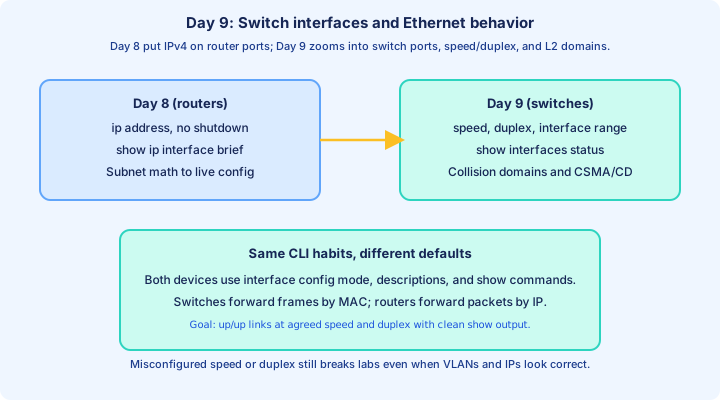
Things we'll cover
We start by contrasting switches and routers—same CLI surface, different forwarding jobs—then walk a topology you can label port-by-port. You will revisit `show ip interface brief` where it applies (SVI, routed ports) and learn the switch workhorse `show interfaces status`.
Configuration sections cover `speed`, `duplex`, and `interface range`. Concept blocks explain full vs half duplex, legacy hubs, CSMA/CD, and collision domains, then tie them to autonegotiation and interface errors you read in `show interfaces`.
By the end you should explain why a half-duplex port on a modern link is suspicious, what late collisions suggest, and how to bulk-configure twenty access ports without typing `interface` twenty times.
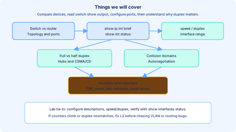
Switch/Router comparison
A Layer 2 switch forwards Ethernet frames using destination MAC addresses. It learns source MACs into a CAM/MAC address table and sends known unicast frames only to the port mapped to that MAC. It floods unknown unicasts, broadcasts, and multicasts (within the VLAN) until it learns better.
A Layer 3 router forwards IP packets using destination IP addresses and routing table lookups. It terminates broadcast domains—broadcasts do not cross router interfaces (unless you later configure helpers or similar). Each routed interface is typically its own IP subnet.
Multilayer switches blur the line (routed SVIs, `no switchport` routed ports), but CCNA still tests the classic split: switch ports connect hosts in a broadcast domain; router ports connect subnets. Day 9 `show interfaces status` is switch-centric; Day 8 `show ip interface brief` is router-centric for physical routed ports.
Exam trap: "Which device breaks up a broadcast domain?" → Router (and VLAN routing on a switch). "Which device creates a separate collision domain per port in full duplex?" → Switch (contrast with a hub).
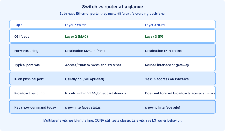
Network Topology
Draw every link with local port, remote device, remote port, and intended speed/duplex. Example: R1 Gi0/0 ↔ SW1 Fa0/3 (router routed port to switch access or trunk—your lab spec decides); PC-A on SW1 Fa0/1, PC-B on Fa0/2, and so on.
Document descriptions that mirror the diagram: `description PC-A` or `description Uplink to R1 Gi0/0`. When `show interfaces status` shows the Name column, that text is what you typed—blank names mean undocumented ports.
One VLAN (often VLAN 1 in early labs) may share a broadcast domain across all access ports. Collision domains on a modern switch are usually one per port in full duplex—a preview of later sections. Keep the router's IP subnet on the uplink consistent with Day 8 math.
Before changing `speed` or `duplex`, note what autonegotiation settled on (`a-full`, `a-100` in status output). After changes, re-run `show interfaces status` on both ends if you control both devices.
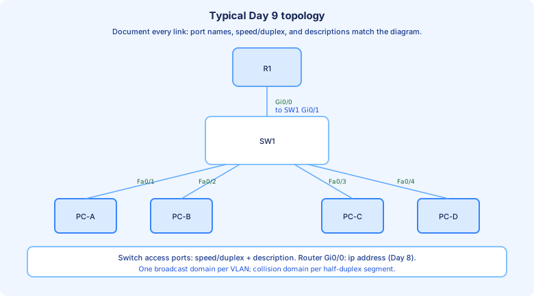
show ip interface brief
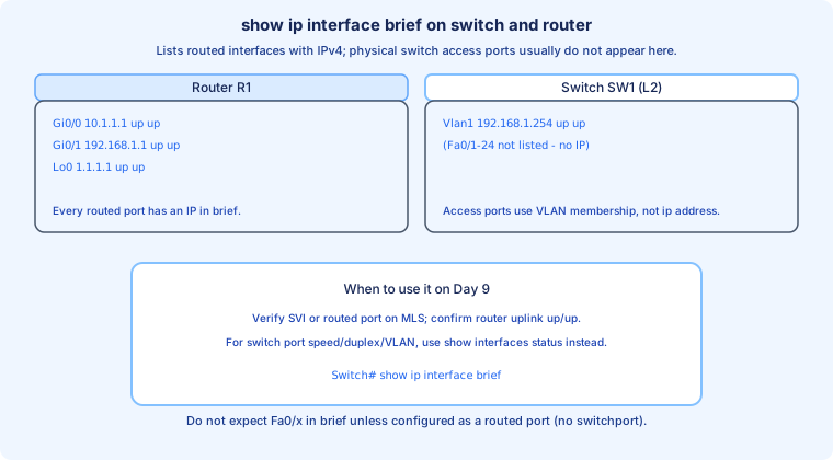
`show ip interface brief` still appears on switches that run Layer 3 features, but it lists routed interfaces with IPv4—typically SVIs like `Vlan1`, management addresses, or `no switchport` routed ports—not every `FastEthernet0/x` access port.
On a pure L2 access switch, expect brief output to show `Vlan1 192.168.x.x up up` while `Fa0/1–24` are absent because they have no `ip address`. Hosts get IP via DHCP or static config; the switch port carries frames, not an interface IP.
On R1, brief still maps `GigabitEthernet0/0` to `10.x.x.x up up` as on Day 8. Use brief on the router uplink and on the switch SVI when you need a quick L3 reachability check; use `show interfaces status` for access-port L2 health.
Commands: `Switch# show ip interface brief` and `Router# show ip interface brief`. Filter: `| include Vlan|up` when hunting the management SVI.
Router vs Switch interfaces
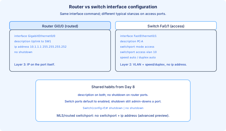
Both devices use `interface <name>` from global config, but the typical stanza differs. Router routed port: `description`, `ip address`, `no shutdown`. Switch access port: `description`, `switchport mode access`, `switchport access vlan <id>`, optional `speed` / `duplex`, and `shutdown` only when intentionally disabling.
Switch ports default enabled on many platforms; router ports often default administratively down until `no shutdown`. A switch `shutdown` shows `disabled` in `show interfaces status`; `no shutdown` returns the port to waiting for link.
Naming matters: IOS is picky—`FastEthernet0/1`, `GigabitEthernet0/1`, not shorthand. `show ip interface brief` and `show interfaces status` display the canonical names—copy from there when configuring.
Preview: `no switchport` on a switch port turns it into a routed port that can take `ip address` like a router interface. That blurs the comparison above; your Day 9 lab usually stays on classic L2 access ports.
show interfaces status
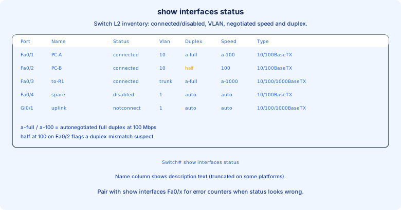
`show interfaces status` (privileged EXEC) is the switch operator's dashboard. Common columns: Port, Name (description), Status, Vlan, Duplex, Speed, Type. It is faster than parsing full `show interfaces` when auditing dozens of access ports.
Status values you must recognize: `connected` (link up, protocol good for L2), `notconnect` (cable unplugged or far-end down), `disabled` (`shutdown` administratively), `err-disabled` (feature violation—port security and others later).
Duplex `a-full` / `a-100` means autonegotiated full duplex at 100 Mbps. Plain `half` at `100` when the peer supports full is a duplex mismatch red flag. `auto` in status often means the port is set to autonegotiate but not yet linked.
This command does not replace `show interfaces Fa0/x` when you need error counters—pair them. Example workflow: status for inventory, then `show interfaces fa0/2 | include error|collision|CRC` on suspect ports.
Configuring interface speed and duplex
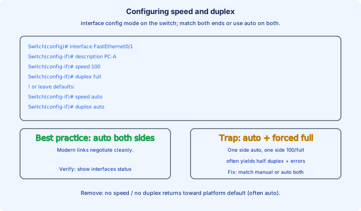
In `interface` configuration on the switch: `speed { 10 | 100 | 1000 | auto }` and `duplex { auto | full | half }`. Platform support varies—Gigabit ports may not allow `speed 10`. `speed auto` and `duplex auto` are common defaults on access ports.
Example manual lock (both ends must match): `Switch(config-if)# speed 100` then `Switch(config-if)# duplex full`. Remove with `no speed` and `no duplex` to revert toward defaults (often auto).
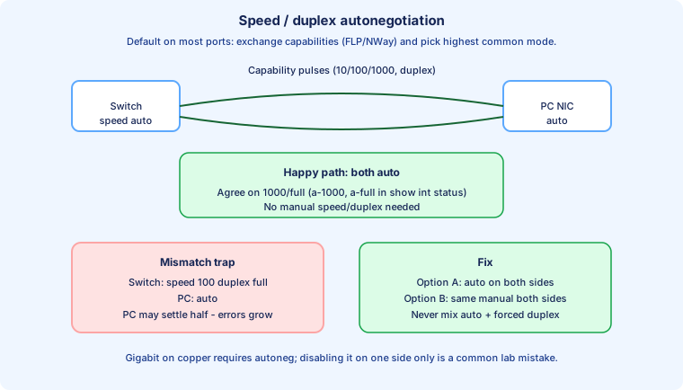
Best practice on modern links: leave auto on both sides unless you have a documented reason to hard-code. Worst practice: `duplex full` on the switch with `auto` on the PC—classic duplex mismatch; link stays up, throughput collapses, late collisions climb.
After changes: `Switch# show interfaces status` and, if problems persist, `Switch# show interfaces FastEthernet0/x`. On routers, `show interfaces` also reports negotiated speed/duplex on Ethernet ports.
interface range
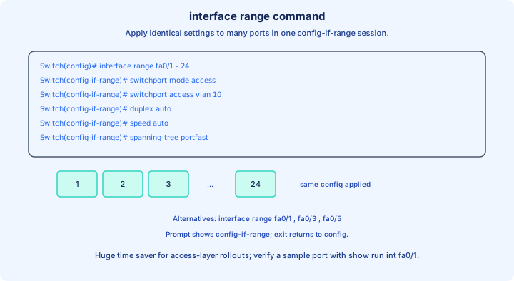
`interface range` applies the same `config-if` commands to multiple ports in one session. Prompt becomes `Switch(config-if-range)#`. Syntax examples: `interface range fa0/1 - 24`, `interface range gi0/1 - 2`, or `interface range fa0/1 , fa0/3 , fa0/5` for non-contiguous lists (platform syntax may vary slightly).
Typical bulk access rollout: `switchport mode access`, `switchport access vlan 10`, `duplex auto`, `speed auto`, and optional `spanning-tree portfast` (when appropriate—know it is for access ports to hosts). One line reaches every port in the range.
Verify a sample port after bulk config: `show running-config interface fa0/1` and `show interfaces status` on a few random ports. A typo in the range (`fa0/1 - 22` instead of 24) silently leaves ports wrong.
Removing settings still happens per command: `no switchport access vlan`, `no speed`, etc., inside the same range context. `interface range` saves time; it also amplifies mistakes—double-check the range before pressing Enter.
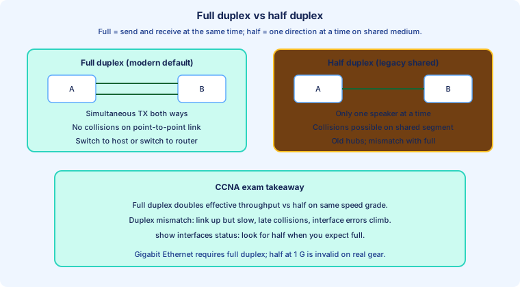
Full/Half Duplex
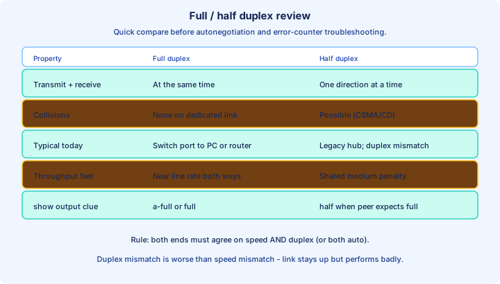
Full duplex: the port may transmit and receive simultaneously on a point-to-point link (switch to PC, switch to router). No Ethernet collisions on that link in proper operation—each direction has its own path in the twisted pair or fiber.
Half duplex: the port either sends or receives at a given moment—like a single-lane bridge. Collisions are possible when two devices talk at once on a shared medium. Required on legacy hub segments; should be rare on switched ports today.
Throughput impact: at the same clock speed (100 Mbps), full duplex can approach 100 Mbps each way; half duplex shares that 100 Mbps in one direction at a time plus collision overhead. Exams love "which duplex allows simultaneous send and receive?" → full.
Operational clue: `show interfaces status` showing `half` on a switch-to-PC link usually means misconfiguration, not intentional design.
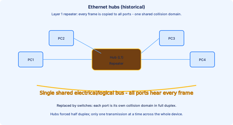
Ethernet Hubs
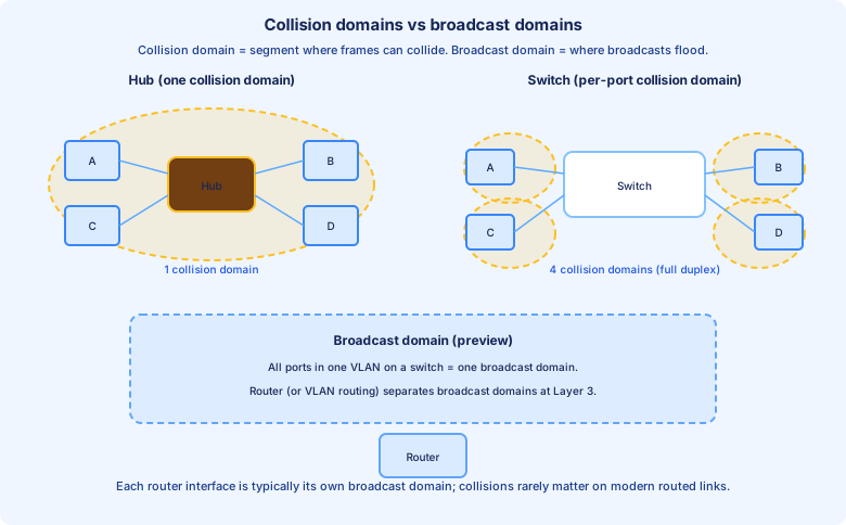
An Ethernet hub is a Layer 1 repeater: bits in on one port are repeated out all other ports. Every attached device shares one collision domain and one broadcast domain. Hubs do not read MAC addresses—they amplify electrical signals.
Because all ports hear every frame, hubs force half-duplex behavior—only one transmission at a time across the shared bus. Collisions were normal; CSMA/CD handled recovery. Hubs are obsolete in production; switches replaced them everywhere.
CCNA still mentions hubs so you understand collision domain exam diagrams: one hub with four PCs drawn inside a single yellow bubble = one collision domain. Replace the hub with a switch and you get four collision domains (with full duplex on each port).
If an old hub appears in a question, assume half duplex, shared bandwidth, and security weakness (every host sees all traffic).
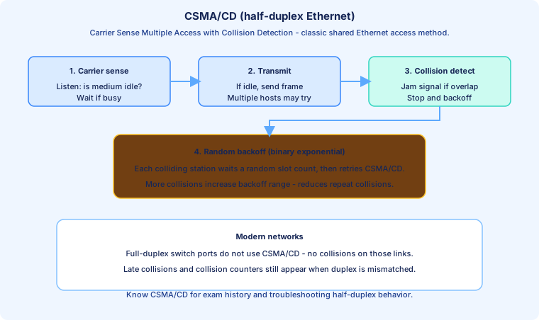
CSMA/CD
CSMA/CD — Carrier Sense Multiple Access with Collision Detection — is the classic half-duplex Ethernet access algorithm. Steps: listen (carrier sense) to see if the wire is idle; transmit if idle; detect collisions while sending; on collision, send a jam signal, stop, and back off randomly before retrying.
Binary exponential backoff increases the random wait range after repeated collisions so stations do not collide forever. Collisions must be detected within the slot time for classic Ethernet; late collisions (reported in `show interfaces`) suggest something is wrong—often duplex mismatch or a faulty segment—not normal contended half duplex.
Full-duplex switch ports do not use CSMA/CD for that link—there is no shared medium to contend for. CSMA/CD remains exam vocabulary and explains collision counters when they appear on misconfigured links.
Modern full-duplex fiber and copper dominate; know CSMA/CD for history, hub diagrams, and interpreting collisions / late collisions in troubleshooting questions.
Collision Domains
A collision domain is the set of devices whose frames can collide with each other on a half-duplex segment. One hub = one collision domain no matter how many ports. A switch creates separate collision domains per port when links run full duplex—collisions should not occur between port 1 and port 2.
Do not confuse with broadcast domain: all ports in the same VLAN on a switch share a broadcast domain unless routing splits them. A router interface boundary (or inter-VLAN routing) separates broadcast domains; it also separates IP subnets.
Exam sketch skill: draw collision domain circles around hub-attached PCs as one bubble; draw separate bubbles on each switch port to a host. Router ports on point-to-point links are typically full duplex with negligible collision concern.
When `show interfaces` reports collisions or late collisions on a switch access port today, treat it as a misconfiguration or hardware defect, not normal CSMA/CD on a healthy full-duplex link.
Full/Half Duplex review
Full duplex: simultaneous TX/RX, no collisions on a dedicated link, expected on switch-to-host and switch-to-router connections today. `show interfaces status`: `full`, `a-full`, or `Full-duplex` in detailed `show interfaces` output.
Half duplex: one direction at a time, collisions possible, tied to hubs and duplex mismatch. Symptom bundle: `half` in status, rising late collisions, CRC, sluggish throughput, ping OK but large transfers stall.
Fix checklist: (1) set both sides to `auto`, or (2) set both sides to the same manual speed and duplex; (3) replace cable; (4) test another port. Never leave one side `duplex full` and the other `duplex auto`.
Gigabit Ethernet over copper requires autonegotiation on standards-compliant links—disabling autoneg on one side only is a common lab foot-gun. When in doubt, `auto`/`auto` on access ports.
Speed/Duplex Autonegotiation
Autonegotiation uses Fast Link Pulse (FLP) / NWay exchanges on the wire so both ends advertise supported speeds (10/100/1000) and duplex modes, then select the highest common capability both can run. Default `speed auto` + `duplex auto` on Cisco switch ports.
Successful negotiation shows `a-100`, `a-1000`, `a-full` in `show interfaces status`. The `a-` prefix means autonegotiated result, not manually configured.
Failure modes: speed mismatch (100 vs 1000) usually prevents link or forces downshift; duplex mismatch (forced full vs auto on peer) often leaves link up at wrong duplex—worse for troubleshooting because status looks partially healthy.
Industry guidance: prefer auto on both ends for access ports. Hard-code only for old devices that negotiate badly—and hard-code both sides identically. Document exceptions in the interface description.
Interface Errors
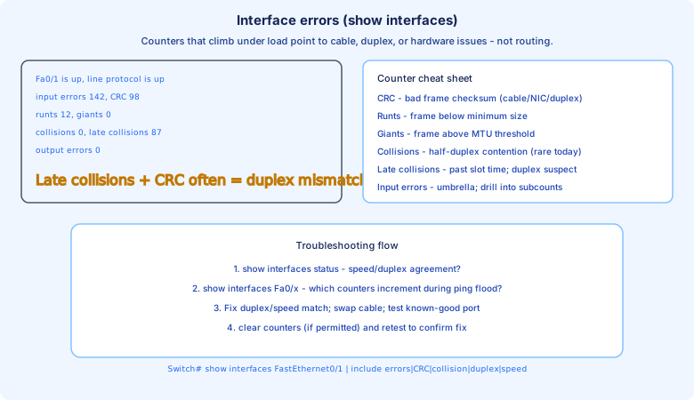
`show interfaces FastEthernet0/x` exposes error counters that `show interfaces status` omits. Watch input errors, CRC, runts, giants, collisions, late collisions, and output errors. Counters should stay flat during normal traffic; climbing numbers under a ping flood indicate physical or duplex problems.
CRC errors: corrupted frames—bad cable, bad NIC, duplex mismatch. Runts: frames below minimum size. Giants: oversize frames (MTU misconfig or hardware issues). Late collisions: strongly suggest duplex mismatch on what should be a full-duplex link. Collisions on a switched access port in production should trigger a duplex audit.
Workflow: `show interfaces status` → identify `half` or odd speed → `show interfaces fa0/x | include error|CRC|collision|duplex|speed` → fix duplex/speed or cable → `clear counters` (where permitted) → retest and confirm counters stay zero.
Do not confuse L2 errors with routing failures. If `connected a-full a-1000` and counters are clean but IP fails, move up the stack (VLAN, gateway, ACL)—Day 9 errors are about the wire, not `ip route`.
Voice VLAN beside the access VLAN
Objective 2.2 treats a phone port as an edge attribute, not as a trunk you design by hand. The access VLAN carries the PC plugged into the phone, untagged. The voice VLAN carries the phone’s tagged frames. On the interface: `switchport mode access`, `switchport access vlan 10`, `switchport voice vlan 20`. The phone learns the voice VLAN from CDP or LLDP, tags its own traffic, and bridges the PC onto the untagged access VLAN. `show interfaces switchport` should list both the access VLAN and the voice VLAN. `show vlan brief` still shows the port in the access VLAN.
A printer, a desktop, or a simple IoT device does not get a voice VLAN. Putting the phone’s VLAN in the access VLAN field, and leaving voice empty, drops the PC into the phone subnet or strands the phone, depending on which device you mis-assigned. Add a description that names the jack and the device. Edge ports should also come forwarding quickly so DHCP is not waiting on spanning tree; PortFast is the STP-day tool for that, and it belongs on host ports.
Exam trap: a voice VLAN is not a second access VLAN and it is not a trunk allowed-list. If the stem shows `switchport voice vlan 20` with `switchport access vlan 10`, the PC is in 10 and the phone is in 20. Verify with `show interfaces switchport` before you rebuild the DHCP pools.
PoE for phones, access points, and IoT
Phones, lightweight access points, cameras, and many IoT devices draw power from the switch. The port can be up at Layer 1 and still leave the device dark if the power budget is exhausted or the port is set to `power inline never`. `show power inline` lists the switch budget, what is already drawn, and the class or watts on each port. A phone that never boots, with the interface not connected or connected and silent, is a power question before it is a VLAN question.
802.3af supplies the original PoE class of power, about 15.4 W at the switch. 802.3at (PoE+) raises that toward 30 W, which is what many access points need. Newer 802.3bt classes go higher for high-draw APs and cameras. You do not memorize every class number. You do read the row that says the port was denied, and you either free budget, move the device to a powered switch, or set `power inline auto` if someone turned the port off. CDP and LLDP let the phone or AP negotiate a more precise draw than the initial class.
Exam trap: a PoE deny looks like a dead device on a live switch. Check `show power inline` and the port’s inline state before you replace the AP or re-address the VLAN. `power inline never` is an administrative choice, and it survives a reload.
Matching the port to the edge device
Desktops, printers, and most IoT endpoints are access ports in one VLAN, with PortFast, a description, and often port security once you reach that day. A controller-based access point is usually an access port too: the AP gets an address by DHCP, builds a CAPWAP tunnel to the WLC, and user SSIDs are switched centrally. It needs PoE and the AP management VLAN. It does not need a trunk of every user VLAN. A standalone AP that maps SSIDs onto local VLANs is the case that needs a trunk.
A virtualization host is the opposite shape. The hypervisor uplink often carries several VM VLANs, so the switch port is a trunk, and a dual-homed host wants a port-channel. LACP `channel-group 1 mode active` on the switch and the matching active mode on the host are what actually bundle; passive facing passive never forms a channel. Day 16 owns the protocol detail. The edge point is that this host is not a printer template: many MAC addresses, a trunk or a port-channel, and no port-security maximum of 1. Firewalls and other appliances follow the same idea. Read the design before you paste the desktop macro.
Exam trap: a lightweight AP on a trunk of all user VLANs, or a hypervisor on an access port in VLAN 1, both come from using one edge recipe everywhere. Objective 2.2 is a list of device types because the port attributes differ. Confirm with `show interfaces switchport`, `show power inline`, and `show etherchannel summary` when a bundle is part of the design.
Things we covered
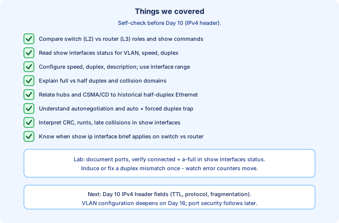
Day 9 connected switch port operations to Ethernet fundamentals: compare switch vs router, read `show interfaces status`, configure `speed`, `duplex`, and `interface range`, and relate hubs, CSMA/CD, collision domains, and autonegotiation to what you see in `show interfaces`.
You should `description` ports, bulk-configure access ports safely, interpret `connected` / `disabled` / `notconnect`, spot `a-full` vs `half`, and explain why duplex mismatch produces late collisions without dropping the link.
Complete the Configuring Switch Interfaces lab with this loop: configure → `show interfaces status` → `show interfaces` on one port → stress-test with ping or copy traffic → confirm error counters. Next up: Day 10 dives into the IPv4 header (TTL, protocol, fragmentation)—Layer 3 theory after this Layer 2 port foundation.
Key ideas
- switchport access vlan carries the untagged PC. switchport voice vlan carries the tagged phone on the same access port. Confirm both with show interfaces switchport.
- show power inline proves the PoE budget and whether a phone, AP, or camera was granted or denied. power inline never leaves the device dark on a live port.
- A controller-based AP is usually an access port in the AP VLAN with PoE. A standalone AP that maps SSIDs to local VLANs, and a virtualization host, often need a trunk.
- Dual-homed hosts use an LACP port-channel with mode active on both sides. A printer template with port-security maximum 1 does not fit a hypervisor.
- Auto on both ends is the normal speed and duplex. Interface descriptions are how the next person finds the jack.
Self-check
- Which commands place data VLAN 10 and voice VLAN 20 on one phone port, and which show lists both?
- An AP never powers up and show power inline says denied. What resource is exhausted?
- Why is a controller-based AP often an access port while a virtualization host uplink is a trunk or a port-channel?
- What do show interfaces status and show interfaces prove about speed, duplex, and errors?