Day 6
IPv4 Addressing
ipv4-addressing
At a glance
Merged former Parts 1–2; public/private troubleshooting emphasis. Binary/decimal comfort, network vs host portions, masks and prefixes, network/broadcast/usables, and why default gateway placement matters. Apply IPv4 to interfaces on routers/switches/hosts; primary vs secondary addressing at the level taught; verification with ping and show commands. Maps to CCNA v2.0 objective(s) 1.3.
Deep chapter
Long-form companion reading (original prose).
IPv4 Addressing — consolidated study day
This day merges former Days 7, 8 into one CCNA v2.0-aligned segment.
Read straight through; use the practice hub (subnetting / CLI) to drill the verbs Troubleshoot, Diagnose, Configure, and Interpret.
From former Day 7
Source material retained from the previous Day 7 chapter for continuity.
Introduction
Day 7 is the arithmetic foundation for everything routing-related in CCNA: IPv4 addresses, binary and hexadecimal, subnet masks, and the three addresses every subnet has—network, usable hosts, and broadcast. Day 6 showed how frames move on a LAN; Day 7 explains how hosts and routers decide whether two IPs are on the same subnet and what numbers you may assign.
You will not configure OSPF today, but you will understand why a default gateway must live in the host’s subnet and why a wrong mask makes ping fail even when cables are perfect. Treat this day as daily reps: short drills beat one long cram session.
Intro to Routing
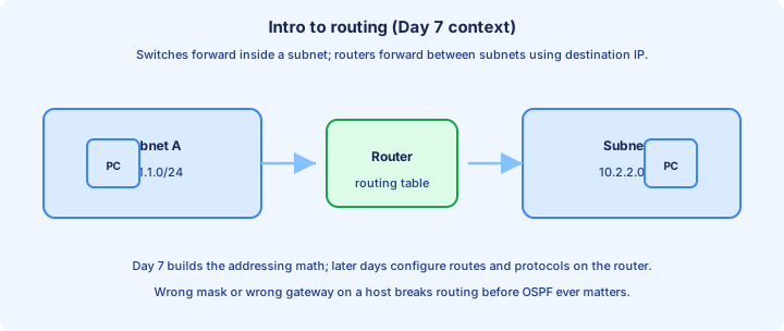
Routing is the process of selecting a path for IP packets between different IP subnets. A router (or multilayer switch doing routing) examines the destination IPv4 address, looks up a routing table, and forwards the packet out an interface toward the next hop. Switches do not route in the CCNA sense—they forward frames within a broadcast domain.
Hosts on the same subnet talk directly (ARP, then Ethernet). Hosts on different subnets send traffic to a default gateway—usually a router interface IP on their own subnet. The gateway then routes toward the remote subnet.
Day 7 focuses on how subnets are defined (mask, network, broadcast). Later days add static routes, dynamic routing protocols, and CLI verification.
IPv4 Header
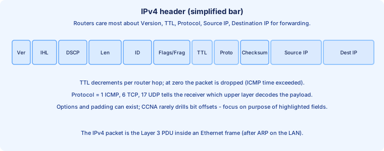
An IPv4 header precedes the payload (TCP, UDP, ICMP, etc.). At CCNA depth, know Version (4), TTL (decremented per router hop; at zero the packet is dropped), Protocol (6 = TCP, 17 = UDP, 1 = ICMP), Source IP, and Destination IP.
Routers use the destination IP for forwarding decisions. Hosts use source and destination plus Protocol to demultiplex to the correct socket. Total length and identification/fragmentation fields matter for MTU troubleshooting later.
The IPv4 header is the Layer 3 PDU you saw on Day 3; it rides inside an Ethernet frame after ARP resolves the next-hop MAC on each segment.
IPv4 Addresses
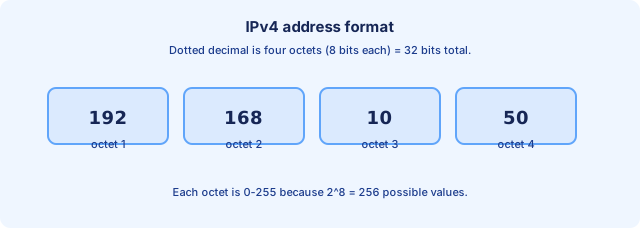
An IPv4 address is a 32-bit number, usually written as four decimal octets separated by dots (dotted decimal), for example 192.168.10.50. Each octet is 8 bits, so each octet ranges 0 through 255.
The address is logical and can change with design (unlike a burned-in MAC). DHCP often assigns host addresses; engineers assign router and server addresses deliberately.
Every device that speaks IPv4 on a subnet needs a unique address in that subnet (NAT complicates the global picture later, but the LAN still needs uniqueness).
Decimal and Hexadecimal review
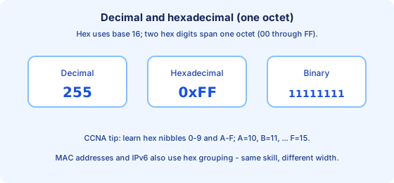
You live in base 10 daily. Networking also uses base 16 (hexadecimal) because one hex digit maps to four bits (a nibble). Two hex digits describe one octet (00 through FF).
Hex appears in MAC addresses (six octets), IPv6, and sometimes in debug output. The digits 0–9 are the same as decimal; A=10, B=11, C=12, D=13, E=14, F=15.
Example: decimal 255 = hex FF = binary 11111111 for one octet. Converting a single octet between decimal and hex is a high-value exam skill.
Binary number system
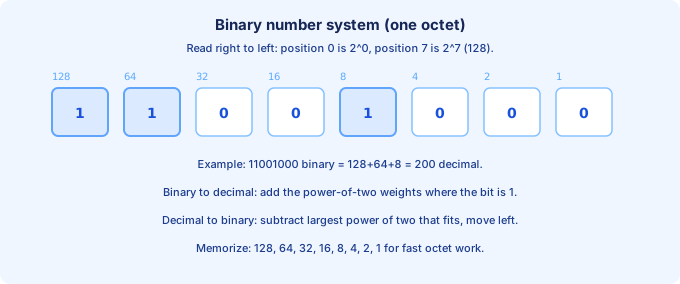
Binary uses only 0 and 1. Each position is a power of two, read right to left starting at 2^0. For one octet the weights are 128, 64, 32, 16, 8, 4, 2, 1.
A 1 in a position means add that weight; a 0 means skip it. Example: 11001000 = 128+64+8 = 200 decimal.
Subnet masks are contiguous 1 bits on the left and 0 host bits on the right when drawn in binary—that pattern is why “/24” means twenty-four network bits.
Binary to Decimal conversion practice
Method: scan the eight bits left to right (or right to left using weights). Add every weight where the bit is 1. Ignore zeros.
Drill examples: 00001010 = 8+2 = 10. 11110000 = 128+64+32+16 = 240. 10100000 = 128+32 = 160.
When an entire address is given in binary on an exam, convert one octet at a time rather than treating 32 bits as one giant number.
Decimal to Binary conversion practice
Method: start at the largest weight that fits (128 for an octet). If the decimal is greater or equal, write 1 and subtract; otherwise write 0. Move to the next smaller weight until you process all eight positions.
Example: 200 decimal → 200≥128 (1, remainder 72) → 72≥64 (1, remainder 8) → 8≥8 (1, remainder 0) → remaining bits 0 → 11001000.
Practice converting random octets until you can produce eight bits in under a minute—speed matters on timed exams.
IPv4 Addresses (network portion, host portion)
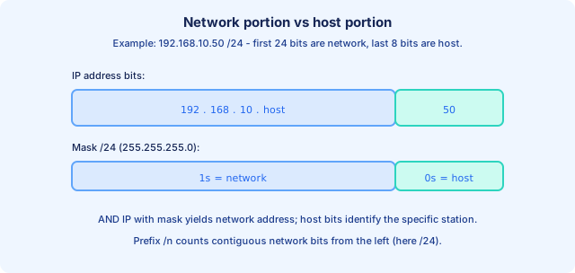
A single IPv4 address splits into a network portion and a host portion. The subnet mask (or prefix length /n) tells you how many bits on the left are network bits; the remaining bits identify the host on that subnet.
Example 192.168.10.50 /24: the first 24 bits are network (192.168.10); the last 8 bits are host (50). All hosts with the same network bits are on the same subnet (same VLAN/broadcast domain in simple topologies).
The bitwise AND of IP with mask yields the network address. Host bits must not be all-zeros (network) or all-ones (broadcast) when assigning to a host—those are reserved.
IPv4 Address Classes
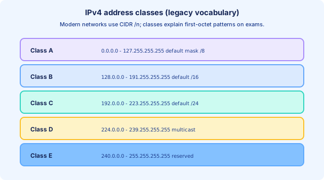
Historically, IPv4 used classes A, B, C, D, E based on the first few bits of the address. Class A starts with 0 (0.0.0.0–127.255.255.255, default mask /8). Class B starts with 10 (128.0.0.0–191.255.255.255, default /16). Class C starts with 110 (192.0.0.0–223.255.255.255, default /24).
Class D (1110…) is multicast. Class E is reserved. Modern networks use CIDR and /n instead of classful boundaries, but exams still use class language for default masks and first-octet recognition.
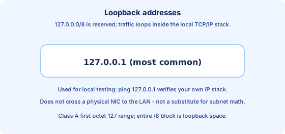
If the first octet is 127, the address is in the loopback range (special case of Class A space)—not used as a normal LAN subnet.
Loopback Addresses
127.0.0.0/8 is reserved for loopback. The most famous address is 127.0.0.1—traffic to it stays inside the local TCP/IP stack and does not hit the LAN NIC for delivery to another machine.
Use ping 127.0.0.1 to test whether your own IP stack is working. It does not prove VLAN, mask, or gateway correctness toward other hosts.
Any address 127.0.0.1 through 127.255.255.255 is loopback-capable on many stacks; still, 127.0.0.1 is the convention you will see in labs and documentation.
IPv4 Address Classes continued
Classful vs classless: In classful thinking, a Class B address like 172.16.5.10 implied a /16 mask whether you needed it or not. CIDR (Classless Inter-Domain Routing) lets you use any prefix length that matches the design, such as 172.16.5.10/24 or 172.16.5.10/30.
Private RFC1918 space is not a “class” but shows up constantly: 10.0.0.0/8, 172.16.0.0/12, 192.168.0.0/16. These ranges are not routed on the public Internet; NAT maps them outward at the edge.
When you see 224.x.x.x, think multicast (Class D)—not a host address to assign to a PC.
Netmasks
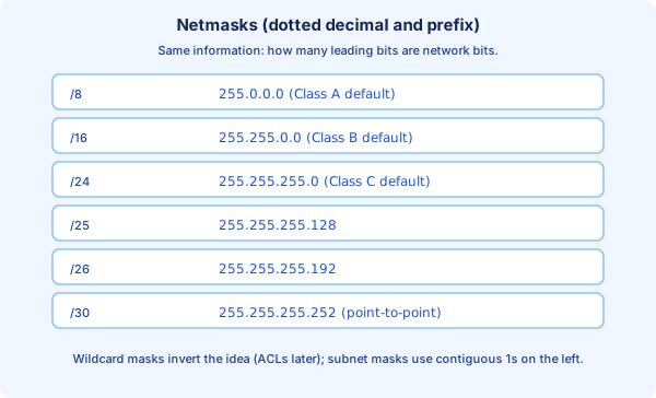
A netmask (subnet mask) is 32 bits with contiguous 1s on the left (network) and 0s on the right (host). Written in dotted decimal, common masks include 255.0.0.0 (/8), 255.255.0.0 (/16), 255.255.255.0 (/24), 255.255.255.128 (/25), 255.255.255.192 (/26), and 255.255.255.252 (/30) for point-to-point links.
Prefix length /n counts the network bits: /8 = 8 ones then 24 zeros; /16 = 16 ones then 16 zeros; /24 = 24 ones then 8 zeros. Mask and prefix are the same information in two notations.
A host configured with the wrong mask may think a remote IP is local (no gateway used) or remote (gateway used incorrectly)—symptoms look like “random” connectivity failures.
Network Address
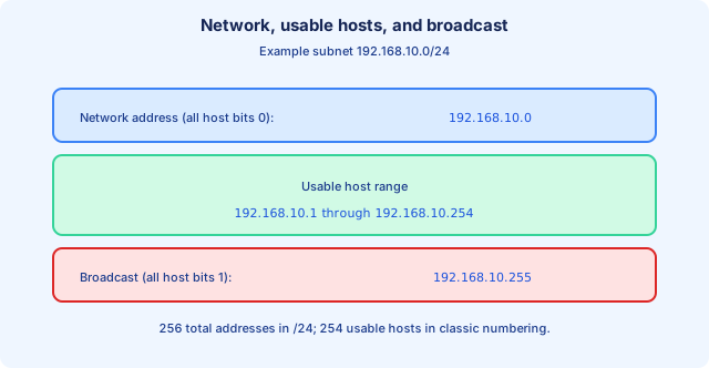
The network address is the IPv4 address with all host bits set to 0. It identifies the subnet itself, not a assignable host. Example: 192.168.10.0/24 is the network address for that /24.
Compute it with IP AND mask. You cannot assign the network address to a PC interface—it represents the wire/subnet identity in documentation and routing tables.
In routing tables you often see prefixes like 192.168.10.0/24 meaning “the subnet” rather than one host.
Broadcast Address
The broadcast address has all host bits set to 1. For 192.168.10.0/24, the broadcast is 192.168.10.255. A packet sent to this address is delivered to all hosts on that IP subnet (mapped to Ethernet broadcast at Layer 2 on the LAN).
You cannot assign the broadcast address to a host. Directed broadcast to remote subnets is often filtered on modern networks for security.
Usable hosts sit between network and broadcast: for /24, typically .1 through .254 (254 hosts) unless design reserves some addresses.
From former Day 8
Source material retained from the previous Day 8 chapter for continuity.
Introduction
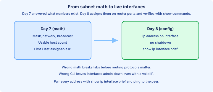
Day 8 turns Day 7’s subnet arithmetic into live configuration: you assign IPv4 addresses to router interfaces, document links with descriptions, and prove correctness with show commands and ping. Day 7 told you which numbers are legal on a subnet; today you put those numbers on `GigabitEthernet0/0` and confirm the box agrees.
Router ports often ship administratively down (`shutdown`). An interface can have a perfect `ip address` line and still fail every ping until you type `no shutdown`. Likewise, a host with the wrong default gateway or mask fails before routing protocols enter the story—carry Day 7’s network/broadcast rules forward while you practice CLI.
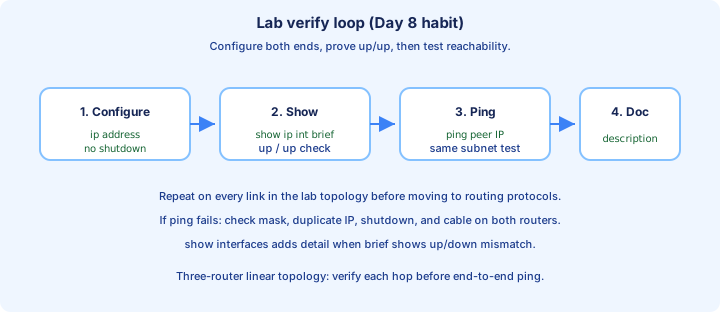
Treat the lab as repetition: configure both ends of each link in the same subnet, verify `up/up` in `show ip interface brief`, then ping the far-end IP. That three-step habit survives every future troubleshooting chapter.
What we'll cover
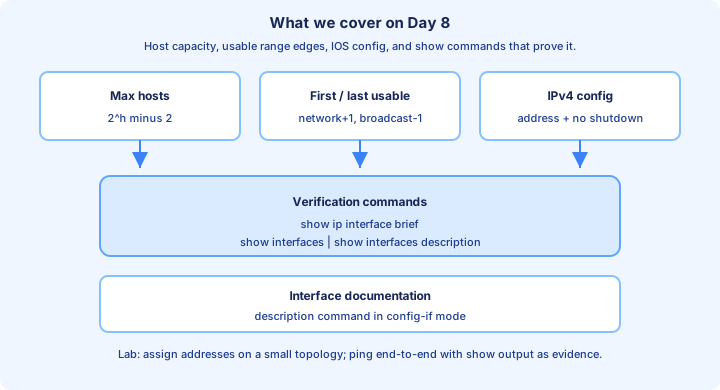
Today’s arc moves from capacity formulas (how many hosts fit in a prefix) to edge addresses (first and last assignable IP), then into IOS configuration and the show commands operators use to audit interfaces without reading entire running configs.
You will configure `ip address` and `no shutdown`, add `description` text for documentation, and interpret output from `show ip interface brief`, `show interfaces`, and `show interfaces description`. The lab ties it together on a small multi-router topology.
If a topic feels like review from Day 7 (network and broadcast), use today to speed up: the exam often pairs subnet math with misconfigured interfaces in the same scenario.
Maximum hosts per network
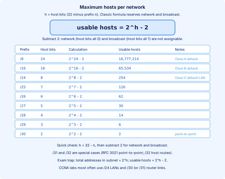
Given prefix length /n, host bits h = 32 − n. The classic usable host formula is 2^h − 2 because the network address (all host bits 0) and broadcast address (all host bits 1) are not assigned to end stations.
Examples: /8 has h = 24 → 16,777,214 usable hosts (Class A default mask). /16 has h = 16 → 65,534 usable (Class B default). /24 has h = 8 → 254 usable (Class C default LAN size). /25 → 126, /26 → 62, /27 → 30, /28 → 14, /29 → 6, and /30 → 2 usable addresses—the usual choice for a point-to-point link between two routers.
/31 and /32 break the simple rule on real networks (RFC 3021 uses /31 for some point-to-point links; /32 is a host route). CCNA labs most often stick to /24 LANs and /30 (or instructor-specified /31) WAN-style links—know the 2^h − 2 reflex first.
Exam trap: confusing total addresses (2^h) with usable hosts (2^h − 2). Always read whether the question asks for “addresses in the subnet” versus “assignable to hosts.”
Networks per IPv4 class
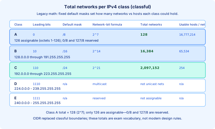
In classful addressing (historical, still on exams), each Class A, B, or C unicast block used a fixed default mask. That mask determines both how many networks existed in the class and how many hosts each of those networks could hold—the previous section covered hosts per network; here we count networks in the whole class.
Class A (leading bit 0, default /8): the network ID is the first octet—7 bits after the class bit → 2^7 = 128 total networks in the class. 126 are assignable for normal unicast use (first octet 1–126); 2 are reserved (0.0.0.0/8 and 127.0.0.0/8 loopback). Each Class A network holds 2^24 − 2 = 16,777,214 usable hosts.
Class B (starts 10, default /16): 14 bits identify the network → 2^14 = 16,384 networks, each with 2^16 − 2 = 65,534 usable hosts. Class C (starts 110, default /24): 21 network bits → 2^21 = 2,097,152 networks, each with 254 usable hosts.
Class D (1110…) is multicast—not counted as assignable unicast networks. Class E is reserved. Modern CIDR ignores these boundaries, but you should recognize class from the first octet and recall the 128 / 16,384 / 2,097,152 total network counts for A / B / C (Class A: 126 assignable, 2 reserved).
First and Last Usable Address
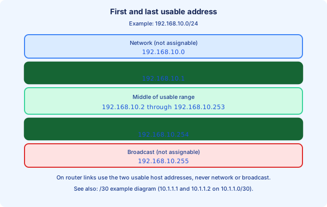
The first usable host address is network address + 1 (in numeric terms on the host portion). The last usable host is broadcast address − 1. Everything between is assignable to PCs, servers, or router interfaces—subject to your design reserving some numbers (for example .1 as default gateway).
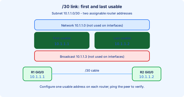
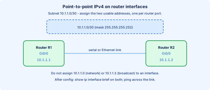
Example 192.168.10.0/24: network 192.168.10.0, first usable 192.168.10.1, last usable 192.168.10.254, broadcast 192.168.10.255. On a /30 link 10.1.1.0/30, usable addresses are typically 10.1.1.1 and 10.1.1.2 with network 10.1.1.0 and broadcast 10.1.1.3.
When cabling two routers, assign the two usable addresses—never the network or broadcast. If both sides pick the same IP, duplicate address detection or simply broken connectivity follows; `show ip interface brief` on both boxes catches many lab mistakes instantly.
Pair this section with Day 7’s AND operation: if you can derive network and broadcast, first/last usable is one step away.
show ip interface brief
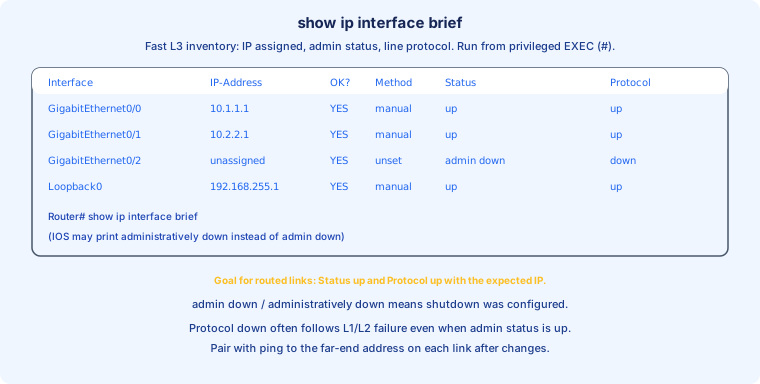
`show ip interface brief` (privileged EXEC `#`) is the fastest map of which routed interfaces have IPv4 addresses and whether each is `up/up`. Columns vary slightly by platform, but you consistently see Interface, IP-Address, Status, and Protocol.
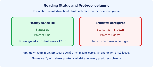
Status reflects administrative state (`up` vs `administratively down` after `shutdown`). Protocol reflects line protocol—often `down` when the cable is unplugged, the far end is down, or L2 never came up. Goal for a configured link: `up` in both columns with the expected IP.
unassigned in the IP column means no `ip address` on that interface yet. `Loopback0` may appear with a stable address used for management or routing ID practice in later labs.
Run it after every change window: `Router# show ip interface brief`. Pipe filters help on busy routers: `show ip interface brief | include up` or `| exclude unassigned` depending what you hunt.
IPv4 Address configuration
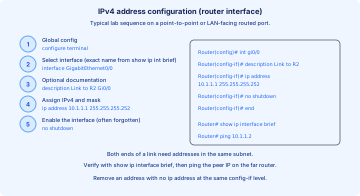
From global configuration: `configure terminal`, then `interface` with the exact name IOS reports ( `GigabitEthernet0/0`, not a guess). Inside `config-if`: optional `description`, then `ip address <ipv4> <dotted-decimal-mask>` (some images also accept `ip address x.x.x.x/n` syntax—follow your lab image). Finish with `no shutdown` on router ports that default to administratively down.
Example point-to-point stanza on 10.1.1.0/30: `ip address 10.1.1.1 255.255.255.252` on R1 and `ip address 10.1.1.2 255.255.255.252` on R2. Mask `255.255.255.252` equals /30. Both routers must agree on the subnet; only the host portion differs.
Remove an address with `no ip address` at the same `config-if` level. `end` or `Ctrl-Z` returns to privileged EXEC; verify with `show running-config interface Gi0/0`, `show ip interface brief`, and `ping 10.1.1.2` from R1.
Hosts (PCs in Packet Tracer) use GUI or `ipconfig`-style settings instead of IOS, but the same rules apply: address, mask, and default gateway on the LAN must be consistent with your subnet design.
show interfaces
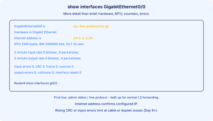
`show interfaces <name>` (for example `show interfaces GigabitEthernet0/0`) prints far more detail than brief: hardware type, MTU, bandwidth, last input/output, and error counters. The first line `GigabitEthernet0/0 is up, line protocol is up` is the headline—both must be `up` for normal routed forwarding on that port.
The `Internet address is …` line confirms the configured IPv4 (sometimes with CIDR suffix). When `up/down` or `down/down`, brief already hinted trouble; `show interfaces` helps distinguish admin down vs carrier lost vs duplex/speed pain (deeper on Day 9).
Watch input errors, CRC, and collisions on access links—nonzero counters climbing under test traffic suggest physical or negotiation problems even when ping occasionally works.
Long output is normal. Filter: `show interfaces gi0/0 | include line protocol|Internet address|errors` or `| section` on platforms that support it (see Day 4 show-filter habits).
show interfaces description
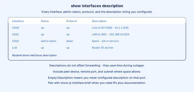
`show interfaces description` lists every interface in a compact table: Interface, Status, Protocol, and Description. It is the documentation view—what you typed with the `description` command in `config-if`, not auto-generated text.
Use it at the start of a lab rescue: identify which port faces which neighbor without tracing cables. A blank Description field means nobody documented that port yet—a common grading deduction in structured labs.
Status/Protocol columns mirror the brief command’s vocabulary: `admin down` means `shutdown` is configured; `up/up` on a routed port you care about is what you want before spending time on routing protocol debug.
This command does not show IP addresses—pair it with `show ip interface brief` when you need both documentation text and L3 assignments in one troubleshooting pass.
Configuring interface descriptions
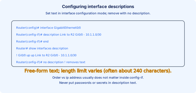
In `interface` configuration mode: `description <free-form text>`. Typical content: remote device name, remote interface, circuit ID, subnet, or VLAN—whatever helps the next engineer. Example: `description Link to R2 Gi0/0 - 10.1.1.0/30`.
Remove text with `no description`. Descriptions do not change forwarding, MTU, or routing—they only appear in `show running-config`, `show interfaces description`, and some management GUIs.
Length limits exist on some platforms (often on the order of 240 characters). Avoid secrets in descriptions (passwords, community strings)—SNMP and config archives leak them.
Build the habit now: every lab link gets a description before you move on to static routes or OSPF in later weeks. Future-you at 2 a.m. will thank present-you.
Topics we covered
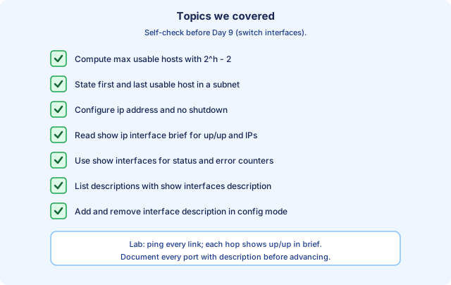
Day 8 connected subnet capacity (2^h − 2 usable hosts) and assignable edges (first/last usable) to IOS interface configuration and verification commands. You should configure `ip address`, `no shutdown`, and `description`, then prove `up/up` with `show ip interface brief` and reachability with ping.
`show interfaces` adds depth when counters or line protocol details matter; `show interfaces description` is your documentation index. Wrong math or forgotten `no shutdown` still tops the list of “mysterious” lab failures—eliminate those before blaming routing protocols.
Before Day 9 (switch port focus), rehearse this chapter on a three-router linear topology: assign /30 (or instructor /31) links and one /24 LAN, document every port, and narrate each hop using only show output and ping as evidence.
Key ideas
- Merged former Parts 1–2; public/private troubleshooting emphasis.
- Prefix /n counts contiguous network bits; mask dotted decimal is the same information.
- Two hosts on different subnets need L3 help to talk (router/SVI).
- Interface must be no shutdown on many platforms; correct subnet on each side of a link.
- Ping tests L3; if ping fails, split L1/L2/L3 evidence with show/ip arp/route.
Self-check
- Given an IP and mask, can you derive network and broadcast without a calculator habit?
- Host default gateway must be an IP on its own subnet — why?