Day 5
Ethernet LAN Switching
ethernet-lan-switching
At a glance
Merged former Parts 1–2. How switches learn MACs, forward vs flood, collision domains vs broadcast domains at a foundational level, and Ethernet frame basics leading into deeper switching. Consolidates switching behavior with lab reinforcement: MAC table behavior, common show commands, and practical verification patterns you will reuse for weeks. Maps to CCNA v2.0 objective(s) 2.1, 2.4.
Deep chapter
Long-form companion reading (original prose).
Ethernet LAN Switching — consolidated study day
This day merges former Days 5, 6 into one CCNA v2.0-aligned segment.
Read straight through; use the practice hub (subnetting / CLI) to drill the verbs Troubleshoot, Diagnose, Configure, and Interpret.
From former Day 5
Source material retained from the previous Day 5 chapter for continuity.
Introduction
Day 5 is Ethernet switching mechanics: how bits become frames, how frames carry MAC addresses, and how a switch learns, floods, and forwards inside a LAN. Every VLAN, STP, and port-security topic later assumes this story is automatic.
Ethernet switching is the engine of local area networks. A switch learns source MAC addresses, forwards known unicast frames to the correct port, and floods unknown unicasts, broadcasts, and (later) selected multicast within a VLAN broadcast domain.
If Day 5 is weak, VLAN troubleshooting becomes guesswork. Day 5 is usually not full STP math yet—that comes soon—but you should already respect that loops make MAC tables lie. It is not inter-VLAN routing yet; picture one VLAN or a flat lab. It is not ACLs.
Close the day with paper mode: draw a switch and three PCs, write MAC table rows as pings happen in different orders, predict flood vs forward, then confirm in Packet Tracer. Prediction first, lab second.
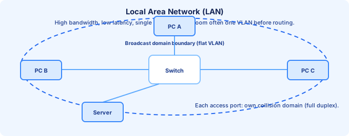
Local Area Networks (LANs)
A LAN is a geographically tight network—office floor, campus building, lab bench—usually offering high bandwidth and low latency. Operationally it is often “everything in this VLAN before we route elsewhere.”
Each switch port in full duplex is typically its own collision domain compared with the old hub world where everyone collided together. The broadcast domain in a flat VLAN is still large: one ARP request can be seen by every host in that VLAN.
A hub repeated electrical signals to every port; a switch forwards frames based on MAC addresses, so different pairs of ports can carry real conversations simultaneously. “Switch” is not a marketing rename of “hub.”
Start the verification habit early: after topology or VLAN changes, plan to run `show mac address-table dynamic` (or platform equivalent), `show interfaces status`, and `show vlan brief` once VLANs exist. Evidence beats guessing.
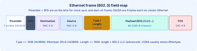
Ethernet frame
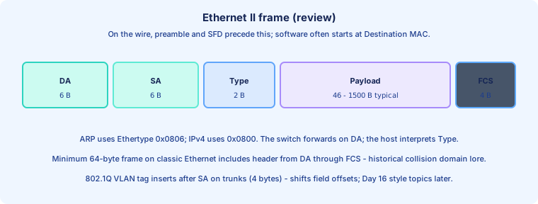
An Ethernet frame is the Layer-2 PDU on IEEE 802 networks. It carries a destination MAC, source MAC, a field that is either EtherType or 802.3 length (CCNA usually stresses Ethertype for IPv4), a payload, and a frame check sequence (FCS) trailer.
Minimum frame size (64 bytes including headers from destination MAC onward on classic Ethernet) guarantees collision detection on half-duplex shared media—historical, but exam lore still references it. Maximum Ethernet payload is 1500 bytes (MTU) unless jumbo frames are explicitly configured.
The switch cares about DA/SA for forwarding; hosts additionally interpret the Ethertype to decide which upper layer (for example IPv4) should process the payload.
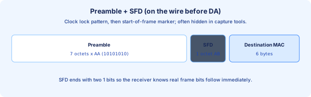
Ethernet frame — Preamble and SFD
The preamble is seven octets of alternating `10101010` patterns (56 bits) that let receivers lock their clocks to the transmitter before real data arrives. It is not part of the frame the NIC typically hands to software.
The Start Frame Delimiter (SFD) is one octet ending with `11` in the last two bits (`10101011`), marking “the next bits are the real Ethernet header starting with the destination MAC.”
You rarely configure preamble/SFD; they matter when you read captures (Wireshark may hide them) or when you think about why interfaces need time to synchronize after idle periods.
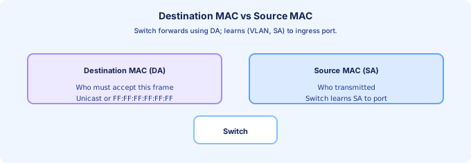
Ethernet frame — Destination and Source MAC addresses
Each of destination and source MAC is 6 bytes (48 bits). The destination selects who must process the frame at Layer 2; the source identifies the sender and is what the switch learns into the MAC address table.
Destination `FF:FF:FF:FF:FF:FF` is the broadcast MAC—every NIC on the VLAN should accept the frame. A unicast destination targets one OUI+NIC combination (with exceptions for anycast-style tricks outside CCNA core).
Switches do not rewrite unicast DA/SA on simple access forwarding (NAT is a different story at Layer 3). When you mirror traffic or troubleshoot, always read DA/SA the way the next hop device will.
Ethernet frame — Type / Length field
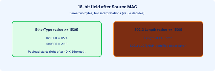
The 16-bit field after the source MAC is interpreted as EtherType when its numeric value is ≥ 0x0600 (1536 decimal)—for example `0x0800` for IPv4, `0x0806` for ARP.
If the value is ≤ 1500, IEEE 802.3 treats it as a length and expects an 802.2 LLC/SNAP header inside the payload to identify the upper protocol—important on paper, less flashy in basic routed-port labs.
802.1Q VLAN tags (802.1Q tag = 4 bytes: TPID `0x8100` + TCI) insert after the source MAC on trunk links; Day 16+ revisits tagging, but know the field order shifts when a tag is present.
Ethernet frame — FCS
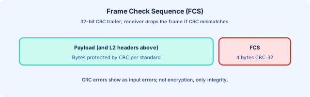
The Frame Check Sequence is a 32-bit CRC computed over the frame fields the standard specifies (conceptually “protect the integrity of what we meant to send”). The receiver recomputes CRC and drops mismatched frames—silent discard from upper layers’ point of view.
CRC errors usually increment input error counters on interfaces. A bad cable, bad optics, or duplex mismatch history often shows up here before you ever debug routing.
FCS is not encryption; it is only integrity. An attacker on the same LAN can still observe frames.
MAC addresses
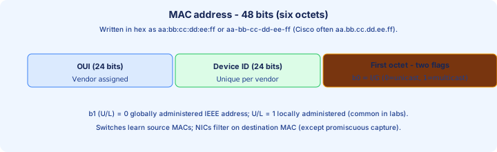
A MAC address is a 48-bit identifier, usually burned in to hardware (BIA) but software-overridable for lab tricks. It is written as six hex octets separated by colons, dashes, or (on Cisco CLI) dots.
The leftmost three octets are the OUI assigned to a manufacturer; the right three are vendor-assigned uniqueness. The least significant bit of the first octet is the I/G bit (0 = unicast, 1 = multicast/group). The U/L bit (second bit) distinguishes globally unique vs locally administered addresses.
Switches index forwarding on destination MAC per VLAN; they learn source MAC → ingress port from every frame.
Decimal number system
Decimal is base 10: each position is a power of ten (… 1000, 100, 10, 1). IPv4 dotted decimal and everyday subnet math still lean heavily on decimal fluency.
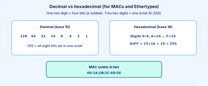
For bitwise work, an octet is just eight binary positions worth 128, 64, 32, 16, 8, 4, 2, 1. Summing the positions where a `1` appears yields the decimal value 0–255—the same range one byte can represent.
Being able to move between decimal and binary for a single octet is enough for many switching labs; hex is the shorthand for writing MACs and Ethertypes compactly.
Hexadecimal number system
Hexadecimal is base 16: digits `0–9` then `A–F` for ten through fifteen. One hex digit = four bits (a nybble); two hex digits = one octet.
Example: `0xFF` = fifteen sixteens + fifteen ones = 255 decimal = `11111111` binary. MAC `AA:BB:CC:DD:EE:FF` is simply six octets written in hex for human eyes.
Cisco `show` output often prints MACs as `aabb.ccdd.eeff` grouped in four hex digits—same value, different punctuation.
MAC addresses (continued)
Locally administered MACs (U/L bit = 1) appear in some virtualization and lab templates; they must still be unique on the broadcast domain to avoid confusing the MAC table.
A device may have many MACs: access ports, SVIs, routed ports, virtual contexts—each needs uniqueness where it attaches.
Security note: spoofing a MAC is trivial in software; port security (later) exists because the data link layer trusts what it hears on the wire.
Unicast frames
A unicast Ethernet frame has a unique destination MAC targeting one receiving NIC (or a path that emulates single-receiver behavior). The switch’s goal is to deliver one copy to the correct egress port once the MAC table knows that mapping.
Unicast is efficient: other ports should not see that payload in a perfect MAC-learned steady state. Contrast with broadcast, which must be replicated to every port in the VLAN (except the ingress port in basic models).
Unknown unicast is still unicast in the frame header—the word “unknown” describes the switch’s table miss, not a different Ethertype.
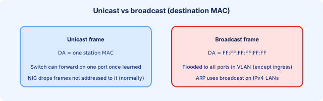
MAC address table and dynamic MAC learning
The MAC address table (CAM) maps (VLAN, MAC) → outbound port. Dynamic entries are learned from source MAC observation; static entries can be configured (later security topics).
Timers age out stale entries when a host goes quiet—first traffic after an age-out often triggers unknown unicast flooding again until relearning completes.
Flapping entries (same MAC jumping ports rapidly) scream loop or duplicate hosts—preview of STP urgency.
Build the CLI reflex: `show mac address-table dynamic` after cable moves or VM migrations; pair with `show interfaces status` for link truth.
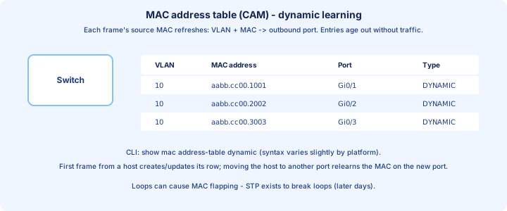
Unknown unicast and flooding
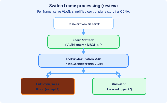
When the destination MAC is not in the MAC table for that VLAN, the switch floods the frame out all other ports in the same VLAN except the ingress port (basic model; advanced platforms can optimize with features you learn later).
That behavior is normal, not a bug—the first ping in a cold lab often generates floods while the table warms. Multicast handling can differ with IGMP snooping; broadcast always floods within the VLAN.
Flooding is expensive at scale—it wastes bandwidth and CPU—so network design limits broadcast domains and keeps loops out with STP.
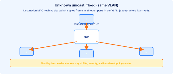
Known unicast and forwarding
When `(VLAN, destination MAC)` hits the table, the switch forwards a single copy out the mapped port. That is the steady-state “fast path” you want in production.
If the destination is on the same port the frame arrived on (two hosts behind a hub, or hairpin scenarios), modern switches typically filter rather than send the frame back out the same access port—another contrast with a repeater hub.
Throughput wins come from simultaneous conversations on different ports once MACs are known—this is the switching fabric story versus shared-medium Ethernet.
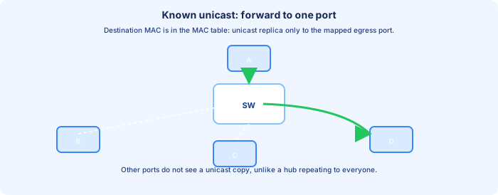
MAC learning and frame flooding / forwarding (review)
Per-frame algorithm (same VLAN, simplified): learn from source MAC → lookup destination MAC → forward to one port if known, else flood (except ingress). Broadcast and unknown-unicast flooding feel similar on the wire; the difference is in the destination MAC value and whether the table had a hit.
ARP broadcasts (`Who has 192.168.1.1?`) populate others’ caches and cause replies as unicasts—pair this mental model with Day 7–8 when IP returns.
Day 6 extends the same ideas: verification, counters, and lab proof that your predictions match `show mac address-table` output.
From former Day 6
Source material retained from the previous Day 6 chapter for continuity.
Introduction
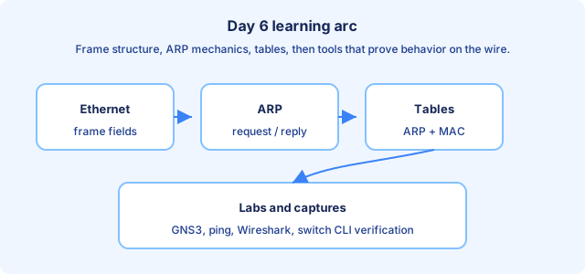
Day 6 connects the Ethernet frame you studied on Day 5 to how hosts actually deliver traffic on a LAN: Address Resolution Protocol (ARP), switch MAC learning, and the lab tools that let you prove each step (GNS3 or Packet Tracer, ping, Wireshark, Cisco show commands).
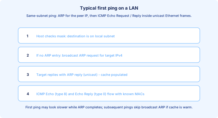
By the end of the day you should narrate this sequence without notes: a host decides a destination IPv4 is on the same subnet, realizes it lacks a Layer-2 address, sends an ARP request as a broadcast Ethernet frame, receives an ARP reply, caches the mapping in its ARP table, then sends ICMP echo traffic (ping) inside unicast Ethernet frames while the switch fills its MAC address table from observed source MAC addresses.
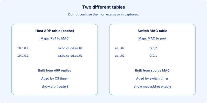
Keep two tables mentally separate: the host ARP cache maps *IP to MAC*; the switch MAC table maps *MAC to port*. Confusing them is a common exam and troubleshooting trap.
Ethernet frame
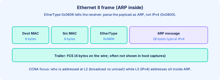
An Ethernet II frame on the lab wire (after physical synchronization) starts with Destination MAC (6 bytes), Source MAC (6 bytes), EtherType (2 bytes), then a payload, then FCS (4 bytes) on the wire. The EtherType tells the receiving NIC which upper decoder to run: 0x0800 for IPv4, 0x0806 for ARP, 0x86DD for IPv6.
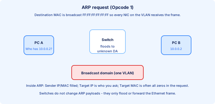
For ARP discussions the critical observation is the outer Destination MAC: broadcast `ff:ff:ff:ff:ff:ff` for a request so everyone on the VLAN sees the frame; unicast for a reply so only the requester (and any monitors) process the payload at full attention.
Switches make forwarding decisions using Ethernet headers. They do not need to understand ARP, but they do flood unknown destination MACs—which is why ARP broadcasts are loud on flat VLANs and why later topics (VLANs, storm control) matter in production.
ARP (Address Resolution Protocol)
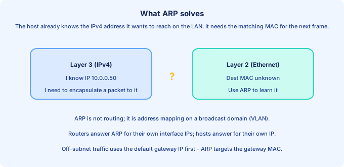
ARP solves a narrow problem: given an IPv4 address on the same broadcast domain, what 48-bit MAC should the NIC place in the next Ethernet frame? It does not discover routes, subnets, or gateways—it only maps addresses for local delivery.
When the destination IPv4 is off-subnet, the host first ARPs (in most stacks) for the default gateway MAC, then ships the packet toward the gateway while keeping the original destination IP in the IPv4 header (NAT changes this story later at the edge).
ARP messages for IPv4 are commonly 28 bytes of payload fields (hardware/type lengths, opcode, sender/target addresses). Opcode 1 is a request; opcode 2 is a reply. Gratuitous ARP (unsolicited announcements) appears in some labs—recognize it as “ARP without a prior request” used for duplicate address detection or cache refresh depending on OS.
ARP Request
In an ARP request, the station that needs a mapping sends an Ethernet frame with Destination MAC = broadcast and EtherType 0x0806. Inside ARP, the Sender MAC/IP identify who is asking; the Target IP is the IPv4 being queried; the Target MAC field is typically all zeros because that is exactly what the sender does not know yet.
Every NIC on the VLAN receives the frame. Hosts whose IPv4 is not the Target IP usually discard the ARP payload after parsing. The owner of the Target IP prepares a reply.
On a switch, unknown broadcast destinations are flooded out all ports in the VLAN except the ingress port (with STP and security nuances later). That flooding behavior is why ARP is visible to Wireshark on a SPAN port or on the sender’s capture even when you are not the target.
ARP Reply
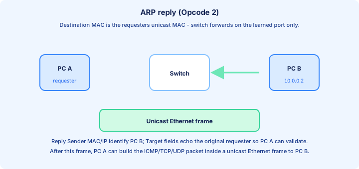
The ARP reply is an Ethernet unicast frame: Destination MAC is the requester’s MAC learned from the request’s Sender MAC field. The switch can now forward instead of flood because the destination MAC is present in (or will be learned into) the MAC address table.
Inside ARP opcode 2, the Sender MAC/IP fields carry the answer: “this is my MAC for this IP.” The Target fields typically mirror the original requester so the receiver can validate context.
After processing a legitimate reply, the requester inserts or refreshes an ARP cache entry. Many operating systems also verify that the same IP is not suddenly advertising a different MAC—security tools expand on that idea; CCNA stays with the baseline mechanics.
ARP Table
On Cisco routers and L3 switches, `show arp` displays the IPv4-to-MAC associations the device has learned or configured. Timers vary by platform; dynamic entries age out so stale mappings do not linger forever after a NIC is replaced.
On Windows, `arp -a` shows the cache; on Linux, `ip neigh` is the modern neighbor view. The important exam skill is reading columns without inventing meaning: IP, MAC, type (dynamic/static), and interface where applicable.
Do not call the switch’s `show mac address-table` output an “ARP table.” The switch is usually not participating in host ARP logic unless it has an SVI or routed port with that IP—in which case it maintains ARP for its own L3 interfaces separately from the CAM table used for L2 forwarding.
GNS3
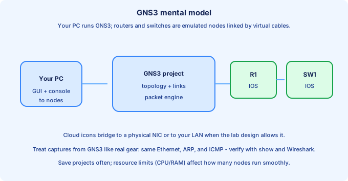
GNS3 is a network emulation lab environment: your computer runs a project that wires virtual Cisco IOS nodes (and other appliances) together. Consoles attach to serial or telnet-style sessions; captures can attach to links depending on design.
Compared with Packet Tracer, GNS3 often feels closer to real IOS images and resource usage—CPU and RAM matter. Save projects, snapshot working configs, and keep a lab notebook of which image version you used so a classmate can reproduce your topology.
For Day 6 objectives, use GNS3 (or your instructor’s mandated tool) to repeat ARP and ping while running Wireshark on a link or on a host cloud attachment. The goal is muscle memory: topology diagram, expected ARP sequence, expected MAC table rows, actual captures, one surprise.
Ping
Ping (ICMP Echo Request, type 8, and Echo Reply, type 0 in IPv4) tests reachability and round-trip delay. It is not TCP; it is carried inside IPv4 (protocol 1 ICMP) inside Ethernet once MAC addresses are known.
The first ping after an idle ARP cache often reveals ARP latency or apparent loss if you misread partial output—some CLIs print one line per probe. On a healthy LAN you expect symmetric ARP then steady replies unless ACLs block ICMP.
Troubleshooting habit: if ping to IP works but ping to name fails, suspect DNS (application/name stack), not ARP. If ping to IP fails on the same subnet, verify masks, VLAN membership, port status, and ARP visibility in Wireshark before chasing routing.
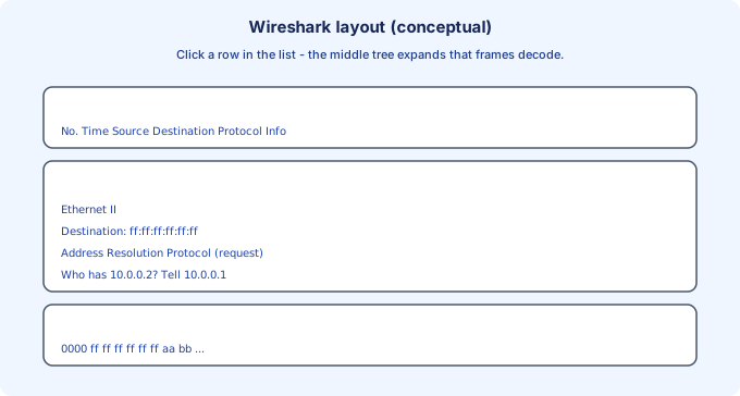
Wireshark packet capture
Wireshark decodes frames into a packet list, a field tree, and raw bytes. Click a row in the list to focus the middle pane; expand Ethernet II to see Destination/Source and Type; expand Address Resolution Protocol to read opcodes and who-has/tell fields.
Useful display filters for today’s labs: `arp`, `icmp`, `eth.addr == ff:ff:ff:ff:ff:ff` for broadcasts, or `arp.opcode == 1` / `== 2` for request vs reply. Filtering reduces noise on busy links.
Remember what you do not see: preamble, SFD, and FCS may be missing from host captures because the NIC strips or offloads them before the OS buffer. That is normal and does not invalidate your ARP analysis.
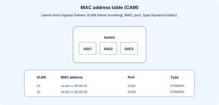
MAC Address Table
A switch learns by copying the source MAC of ingress frames into the MAC address table (content-addressable memory, CAM) keyed by VLAN on enterprise switches. Known unicast destinations forward out a single port; unknown unicast floods within the VLAN; broadcast and multicast (by default) flood within the VLAN.
Use `show mac address-table dynamic` (syntax varies slightly by IOS/XE) to see learned entries. Compare before and after a ping storm between two PCs: you should predict which MAC appeared on which port and in which VLAN column.
If a MAC moves between ports rapidly while you did not physically move cables, suspect loops, NIC teaming oddities, or duplicate IPs—STP and first-hop redundancy chapters formalize some of those failure modes.
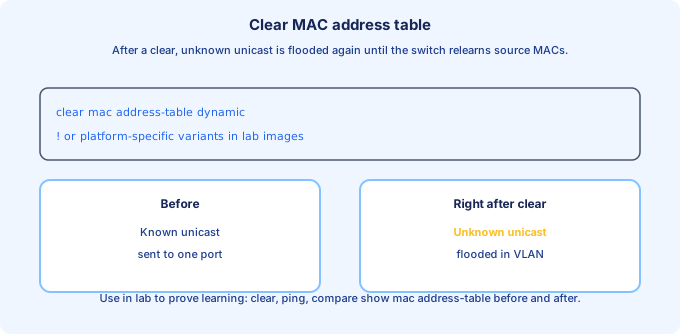
Clearing the MAC Address Table
In lab, `clear mac address-table dynamic` (or the platform equivalent) wipes learned entries. Immediately after, the switch will flood unknown unicasts again until it relearns from new frames—use that behavior to prove you understand learning.
Do not clear tables on production switches without a maintenance window; transient flooding can spike CPU and obscure unrelated issues. In class, coordinate with partners so you do not clear the table while someone is mid-demo unless intended.
Pair the clear with ping and Wireshark: you should see flooding behavior return briefly, then stable unicast once the table repopulates. Document timestamps in your lab notes.
Ethernet Frame review
Close the day by sketching from memory: DA, SA, Type, Payload, FCS order; minimum frame size lore for classic shared Ethernet; where 802.1Q tag inserts on trunks (after SA, shifting offsets).
Reconcile Day 5 field drill with Day 6 behavior: the switch cares about DA for delivery and SA for learning; the host cares about Type to dispatch ARP vs IPv4; ARP then fills the missing DA for the next ICMP ping frame.
Tomorrow (Day 7 in this atlas) pivots to IPv4 subnet arithmetic—carry forward the idea that ARP only helps on-subnet neighbors; off-subnet delivery always involves the gateway and routing tables you will configure in the coming week.
Key ideas
- Merged former Parts 1–2.
- Unknown unicast/multicast/broadcast flooding is normal until learning completes.
- Each switch port is typically its own collision domain in full duplex.
- show mac address-table ties L2 forwarding to observed traffic.
- Symptoms of loops preview STP motivation (coming later).
Self-check
- Why does ARP matter to a switch even though ARP is not 'switch configuration'?
- Can you predict flood vs unicast given a MAC table snapshot?